Continue to Site

Welcome to our site!

Electro Tech is an online community (with over 170,000 members) who enjoy talking about and building electronic circuits, projects and gadgets. To participate you need to register. Registration is free. Click here to register now.

  • Welcome to our site! Electro Tech is an online community (with over 170,000 members) who enjoy talking about and building electronic circuits, projects and gadgets. To participate you need to register. Registration is free. Click here to register now.

connecting 24v transducer to PIC

Status
Not open for further replies.

MrDEB

Well-Known Member
found a transducer for measuring air pressure in an air tank (air cannon project) on ebay.
one problem the transducer requires 15-24 volts and outputs 0 to 10 volts.

this is a DSY-150 transducer

**broken link removed**
what would be best way to connect to 18F452
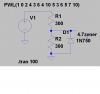
thinking voltage divider ??
still need a 15-24 volt supply. planning on solar cells?
any ideas. Am sure it can be done but how?? and still maintain a sense of accuracy.
perhaps just measure the resistance of without connecting to voltage supply??
 
Use a 24V supply with a 5V regulator for the uC.

Well, there are several ways to interface the transducer to the uC.

The voltage divider is an idea.

Or, you can use a OPAMP/COMPARATOR, to output high/low level when the transducer senses a certain pressure.
 
I want to display the actual pressure

using an LCD 16x2 or a 20x4 display
air pressure for the various targets will need adjustment for distance so a digital readout is essential. sure a tire gauge would work but not real accurate.
not sure how these transducers work but get the idea that it may just output a resistance? but the data sheet says it requires 15ma min at 15-24v
I may call manfacture to get some info.
or just may resort to a voltage divider.
 
boy do I feel dumb

started computing for voltage divider where the voltage is 24 volts and need a min of 15ma.
looked at specs a second time - output is 0-10 volts so all I need is 5 volt output.duh= 2-300 ohm resistors in series will get me just under 17ma.
now wattage??
if I win auction, plan on using 1% resistors. maybe lowering the lower resistor for little less than 5v, like 4.5, just to be safe.
perhaps a zener diode to protect PIC?
but that might affect my voltage reference of 0-10v output from transducer??
 
not sure about using the zener?

will it mess up the voltage output thus screwing up the pressure readings?
if so, suggestions?
 

Attachments

  • voltage divider.PNG
    voltage divider.PNG
    26.2 KB · Views: 329
I think you are confusing some things up:

1 - Your transducer needs 24V @ 15mA to work. (Your psu needs to stand a current of, at least, 15 mA at 24V).

2 - Your transducer will output a 0 - 10V . (You don't need a minimum current to have this output. It will output 0 - 10 V, period. Of course, if you have a low resistance load, you gonna degrade the output level).

3 - 300 ohms is too low, you don't need that. Your uC's analog input is high impedance and will not overload the the voltage divider. Use resistors in 'k' range, like 4k7 .

4 - Protection is a good thing. But remember that zeners begin to conduct before the nominal voltage, so you are going to have a small degration.
 
spec sheet says=

min supply voltage = 15
min supply current = 35ma
min output voltage = 0
max output voltage = 10
the 300 ohm resistors are a voltage divider so output won't exceed 5vdc
I did boo boo as I thought (stupid me on the spec sheet) the output was 15ma but it is supply voltage min. of 15v
supply current is 35ma.
your suggesting going with say 3k resistors on the divider?
at what wattage? I was contemplating 1/2 watt. keep the heat to a min as the heat will change the divider resistance.
the zenier maybe go with a 5 v instead of a 4.6?
I still need to win the auction.

As Colin and I said, for the voltage divider use resistors in k range. Colin says any from 10k to 47k, I say that you can go from 4k7.

4k7, due the uC datasheet specs, that says "The maximum recommended impedance for analog sources is 2.5 kΩ." (page 184, 17.1)

As the source impedance is the 1/2 * voltage divider resistance, with 4k7 you are going to have 2.35 kΩ

Think about it:

If you use the voltage divider with 300 Ω resistors, you are going to drain about 17 mA from the transducer, which I believe that is too much ( near the limit). And the each resistor will dissipate 83 mW.

If you use 4k7 you are going to drain ~ 1.1 mA from the transducer (you won't overload it, so you are going to take much more accurate measurements), and each resistor will dissipate ~ 5.5 mW (1/180) W (so you can use 1/4W or 1/8W instead of 1/2W).

And you can find 0.5% tolerance resistors, if needed.

The zener you can use is 5.1V, but you must test the accuracy of your measurements.
 
this is where I get lost

the subject of impedence.
in the data sheet you say the impedence is 2.5k
what does one do with that figure.
will sim in LT Spice using two 4700 ohm resistors and a 5.1 zener.
Oh after looking over the spec sheet on the transducer, I see it has two adjustments so the output voltage can be adjusted for desired voltage.
just need to win the auction.
 
the subject of impedence.
in the data sheet you say the impedence is 2.5k
what does one do with that figure.
will sim in LT Spice using two 4700 ohm resistors and a 5.1 zener.

Sounds a waste of time? - the PIC input has a minimum source impedance, NOT a resistance, I don't think LTSpice simulates the internal working of a PIC?. Basically it requires a certain amount of source (or sink) current to charge/discharge the capacitor in the internal sample and hold.

If the source impedance is too high, then it slows the rate at which the capacitor charges/discharges. This only really matters (within reason) if you're switching channels - and too high a source impedance will give the wrong reading on both, UNLESS you delay before reading (but after switching channels), to give it time to settle.
 
here is a sim

with 2.5k load or impedance it drops the input voltage.
Nigel, are you suggesting not to worry about impedance.?
I get lost in this area anyway.
I inserted a 6.2 zener.
The transducer has an adjustment for the span of desired voltage output as well as low output level.
may just do the voltage divider then adjust transducer for actual pressure in tank.
 

Attachments

  • voltage divider.PNG
    voltage divider.PNG
    35.1 KB · Views: 160
with 2.5k load or impedance it drops the input voltage.

No, with a 2.5K RESISTANCE it would, but it's not a 2.5K 'resistance', it's not really an impedance either.

It's a high resistance/impedance input pin with a small capacitance across it, it's the charging of that capacitor which determines the maximum source impedance.

Which was why I said you're wasting your time trying to simulate it in that way.

Nigel, are you suggesting not to worry about impedance.?

How fast are you switching input channels?, or are you at all?.
 
description of events

using a 18F452 displaying wind speed and direction on 20x4 LCD
using the transducer to measure/indicate the air pressure in the air cannon air chamber.
using this data (wind speed, direction, muzzle velocity (two IR sensors 1 foot apart mounted on the barrel) then determind desired air pressure to hit targets at 30, 60,90 yards then shoot for distance.
As far as the transducer doing any fast switching, I think not. All it's doing is indicating air pressure in the cannons air chamber.
have a rotary switch to select which display I desire
DISPLAY 1 = wind speed and direction
DISPLAY 2 = air chamber pressure
DISPLAY 3 = muzzle velocity after firing
using the outputs of all this data, we should be able to determine what pressure to use for a desired distance.
note the data specs on the transducer says the output is adjustable

DS Series Custom Pressure Transducers | Pressure Sensors | Proportion-Air

the transducer is a DSY-150
supply voltage 15-24v
supply current min = 35ma
output = 0-10v but is adjustable
 
now theres a question
why is it called attenuator.?
another word for voltage divider output or ??
just waiting for 5:13pm today as the auction on the transducer is ending.
these puppies sell for $200+
hoping for under $10 + $10 shipping.
 
Status
Not open for further replies.

Latest threads

New Articles From Microcontroller Tips

Back
Top