Continue to Site

Welcome to our site!

Electro Tech is an online community (with over 170,000 members) who enjoy talking about and building electronic circuits, projects and gadgets. To participate you need to register. Registration is free. Click here to register now.

  • Welcome to our site! Electro Tech is an online community (with over 170,000 members) who enjoy talking about and building electronic circuits, projects and gadgets. To participate you need to register. Registration is free. Click here to register now.

Connecting 156 leds in series

Status
Not open for further replies.

Freaktron

New Member
How can I connect 156 led in series using 220v/ac or some other rating/dc.
Here are the factors:
Blue or white leds 3,2-3,6v, 20 mA each.

Please describe in detail "how to" either for AC or DC.
Thank you VERY much! :)

FT
 
How can I connect 156 led in series using 220v/ac or some other rating/dc.
Here are the factors:
Blue or white leds 3,2-3,6v, 20 mA each.

Please describe in detail "how to" either for AC or DC.
Thank you VERY much! :)

FT

hi,:)
If you multiply 156 * 3.5V you get a 546Volt drop, so the first answer is you cannot connect them in series using 220Vac/dc.

Tell us what your project is about, we may suggest alternatives..
 
Last edited:
I wanna make a led steady lettering wich uses those 156 leds.

It's possible workaround the 546v by spliting the series in 2: 78*3=234v :confused:

Where I work there are those letterings and I know that they use plain AC.
 
I wanna make a led steady lettering wich uses those 156 leds.

It's possible workaround the 546v by spliting the series in 2: 78*3=234v :confused:

Where I work there are those letterings and I know that they use plain AC.

hi,
This is one way.
Three identical chains of 52 LED's

The LED's must be able to carry 12mA average and 40mA peak currents.

NOTE: this circuit is NOT isolated from the mains supply.
 

Attachments

  • esp01 Sep. 30.gif
    esp01 Sep. 30.gif
    4.6 KB · Views: 469
Last edited:
I suggest a full-wave bridge rectifier from the mains connected to three chains of 52 LEDs in parallel. That way the diodes would have less flicker and the peak current to average current ratio is reduced. Each chain would have a 4K7Ω, 2W resistor in series, which would give a peak diode current of about 27mA and and average current of 17mA.

NOTE: Circuit NOT isolated from AC mains.
 
hi,
This is one way.
Three identical chains of 52 LED's

The LED's must be able to carry 12mA average and 40mA peak currents.

NOTE: this circuit is NOT isolated from the mains supply.

You could remove the resistors and connect two chains of the resistors in reverse parallel for two out of the three strings.

Actually, if you're just planning to use 220V AC and not DC you could use two strings of 78 LEDs in reverse parallel. The peak voltage off 220VAC is 311V which is gives a wide enough margin on the toal forward voltage of 273V.
 

Attachments

  • 102 mains LEDs.GIF
    102 mains LEDs.GIF
    5 KB · Views: 322
What about using AC LED's, I don't know much about their operation or life specs. might be expensive being infant technology.
I would like to learn more about these to asses suitability.

I have only seen promotional material on Seoul Semiconductor ES Acriche AC LED's.

& also on Australian New Inventers there were some AC LED's (array of) that connected directly to mains Voltage.
I Tried to research these but came up blank.
 
There's nothing new about AC LEDs.

They're just LEDs with two wired back to back.

Unless you're talking about the high powered type which are just power LEDs with built-in switched mode power supplies.
 
Ok I have had a look at the datasheet for the Acriche LED AX2200.

The spec is 20mA(RMS) & 720R resistor with operating voltage of 100Vac. That equates to 85.6V RMS operating voltage of the LED.
Yes they have 4 dies inside (looking at the picture), you may be right hero & they have a smps inside (pretty small 8mm dia) but that would defeat their claim of "no energy losses in power conversion".

I should have looked this up before posting as this is no good for a string of LED's for a sign as each LED is nom 20mA & high VF.

Im going to ask some questions of Seoul Semi on the Acriche & see waht they will say (there is no detailed operation info on their web)
 

Attachments

  • Acriche.jpg
    Acriche.jpg
    269.3 KB · Views: 273
Deleted by author!!!
 
Last edited:
Warning Lethal Voltage:
If you do not have experience of safety relating to all aspects of direct mains operated circuits , do not use this design.


----------------------------------------------------------------------

I hope this doesn't confuse, I have run a quick simulation with LTspice & attached output for reference.
The circuit uses a bridge rectifier as previously mentioned in this topic & a series resistor for "tuning" LED string current. 2 strings of 78LEDs each.
The 47uF capacitor increases RMS current to LEDs from 16 to 19.7mA per string but is not absolutely needed.

The Series LED string of 78 LED's is represented by a 13k954 resistor to aproximate the LED string (Willbe helped here), too much time to make the white LED spice component.

The GND symbol on the schematic is for simulation reference only !!!

I set the power source to 240Vac (sorry forgot you had 220V) but just adjust R3 & R4 if needed.

I feel having the bridge rectifier (use 1kV) is better as it blocks reverse voltage to the LED's mainly during high mains voltage surge.

Finally, I would add a Tranzorb (eg:1.5KE400) in parallel with C1 to help protect against transient high voltage (another benefit of the resistor(s) R3, R4)

This circuit is a slightly more complex but should be reliable (5 Components is still few).

Need to be careful with LED's powered from the mains, even at Catedory 1 rating (final user equipment) there is plenty of energy to cause the epoxy of an LED to completely carburise & if this is poking thru a panel it can be live carbon.


Files attached:
Screen dump of Simulation
LT Spice sim file .ASC
 

Attachments

  • 78 White LED's sim.gif
    78 White LED's sim.gif
    84.5 KB · Views: 348
  • Test AC leds Rect.asc
    1.9 KB · Views: 202
156 leds

"so the first answer is you cannot connect them in series using 220Vac/dc."

I beg to differ with you, you can connect them in series, they just won't light! lol:):p:D
 
The Series LED string of 78 LED's is represented by a 13k954 resistor to aproximate the LED string (Willbe helped here), too much time to make the white LED spice component.
A resistor does not make a good simulation model for an LED. Better would be a zener with a breakdown voltage equal to the sum of the LED voltages. Using a 3.5V drop for the 78 LEDs in this example would require a zener of 273V.

Also each LED string should have it's own series resistor to minimize current hogging.
 
Also each LED string should have it's own series resistor to minimize current hogging.

Not if they're connected in reverse parallel(see the schemaic I attached to my previous post)), which they should be as it both saves energy and components.
 
Also each LED string should have it's own series resistor to minimize current hogging.

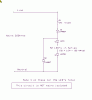
In practical applications LED's current share quite well due to temperature/current/VF characteristics, have a look at the attached "LED array,pdf" (Green LED's), we use this scheme (as well as other similar) for LED Signals in Rail transport.
The cross connection improves redundancy against open or high Vf LED's. A common failure mode in LED's we encounter.

A resistor does not make a good simulation model for an LED. Better would be a zener with a breakdown voltage equal to the sum of the LED voltages. Using a 3.5V drop for the 78 LEDs in this example would require a zener of 273V.

Agreed,
The simulation is for aproximation only, As vell as Forward Voltage drop, Also some parasitic resistance needs to be included as the specific VF for LED's is current & temperature dependant.
When feeding an LED from a fairly stable/smooth Voltage & resistive source impedance, the characteristic of current & subsequent Vf can be aproximated with a resistor fairly well for the purpose of getting a ball park figure.
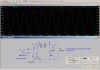
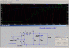
In the gif attached the blu trace is 13k9 resistor & Grn trace is the LED string.
For 78 LED's I made a new spice component & have aproximated 350R for the parasitic resistance (roughly estimated from osram white LED datasheet)
LTspice doesn't always accomodate changes in the circuit when running a simulation, it's probably my fault but I close & reopen & it fixes.

I have included LTspice files attached, the standard.dio file needs '.txt' removed (this has the LED string component with 280Vf)
I tried to include parasitic resistance in the spice component but ran out of time to get it working properly. (Im still learning - keeps the brain healthy)
 

Attachments

  • 78 White LED's  2 sim.gif
    78 White LED's 2 sim.gif
    89.7 KB · Views: 207
  • standard.dio.txt
    7.7 KB · Views: 339
  • Test AC leds Rect 2.asc
    2.1 KB · Views: 166
  • LED Array.pdf
    16.4 KB · Views: 221
Status
Not open for further replies.

New Articles From Microcontroller Tips

Back
Top