Continue to Site

Welcome to our site!

Electro Tech is an online community (with over 170,000 members) who enjoy talking about and building electronic circuits, projects and gadgets. To participate you need to register. Registration is free. Click here to register now.

  • Welcome to our site! Electro Tech is an online community (with over 170,000 members) who enjoy talking about and building electronic circuits, projects and gadgets. To participate you need to register. Registration is free. Click here to register now.

connect 3 small wind turbines to gain higher voltage?

Status
Not open for further replies.

GoVertical

New Member
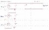
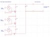
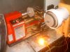
Hi, I fabricated 3 small VAWT that produce 5 amps at 16 AC. Is there a circuit configuration that will connect the three together so I can use them to charge a battery bank at 12 volts DC?

I was thinking convert the AC to DC and connect them in series. I do not have a lot of experience with power circuits and any help would be greatly appreciated.
 

Attachments

  • 0009[0].JPG
    0009[0].JPG
    18.3 KB · Views: 903
  • MultiUpload.jpg
    MultiUpload.jpg
    16.2 KB · Views: 1,277
The schematic you've posted is far too small to see.

16VAC is 22.6V peak which will be converted to 22V by the rectifier so I would recommend connecting them in parallel. 22V will overcharge the batteries if the current is high enough so perhaps you should consider adding a regulator.
 
I think just rectifying the AC and putting all three in parallel would work just fine. You will likely need a shunt type voltage limiter of some sort to keep the battery voltage reasonable.

So what did you make them out of? And what did you use for the generator?
 
I made a mistake

Hi, output is 16 volts AC peak to peak. After I convert to DC I only get 8 volts. Here is a larger picture of the circuit.
 

Attachments

  • BigCircuit.jpg
    BigCircuit.jpg
    93.7 KB · Views: 1,412
16V peak should give 14V peak minimum which is fine for charging 12V batteries.

D5 to D7 aren't needed and are connected in backwards so it's no surprise that the output voltage is really low.:D
 
If your getting 8 volts after rectification is there a bad diode or one connected back wards, or not connected at all?
As stated earlier 16 volts AC should give you a 22 volt peak assuming you have an AC sine wave coming from the source that is.
A near square wave would still be about 16 volts when rectified but if your using a cheap meter a non sine wave power source will not give you an accurate AC voltage reading.

Is the 5 amps output at a short or at a specific load voltage?
 
Hang on he said 16V peak-to-peak which is 8V peak so he is right, he will get 8VDC minus any rectifier losses.

Three generators in series will give 24VDC.

Rather than connecting them in series he could add a voltage doubler to each and connect the outputs in parallel.
 
test load

Hi, the test load I am using is auto head light with a internal resistance of about 2.7 ohms. I connected it to a variable speed lathe and the multi-meter was set to read AC and it displayed 16 volts at about 700 RPMS. Then I checked current and the permanent magnet alternator was producing about 5 amps.

It has been a few years since I used the multi-meter but after the responses I have received it maybe time to review its operation.

I rectified the AC single and read 8 volts DC. I have no experience with generator circuits, but what I am trying to do is connect the three single phase alternator in series to achieve a higher voltage.

If I am reading the meter wrong then yes connecting them in parallel would be the right approach.

I am still very interested in finding a circuit that will allow me to connect them series. Any help would be greatly appreciated. Thanks to all for all the feedback.


Can a voltage doubler circuit handle the current at 5 amps?
 

Attachments

  • 68coils.JPG
    68coils.JPG
    57.1 KB · Views: 1,511
  • 0002.JPG
    0002.JPG
    48.6 KB · Views: 1,533
That looks impressive, did you make it yourself?

It's probably too late now but I would have gone for a three or even six phase design because it will give a smoother DC output.

The meter normally measures in RMS so the peak voltage will be 16√2 = 22.6V.

Do you have a filter capacitor connected to the output?

You should be getting 21V out otherwise you have a problem.
 
no cap connected

Hi, I did make them. They are easy to fabricate. The only restriction is the diameter of the housing it limit’s the number of coils and the size of the magnets. I have larger PVC fittings that will allow me construct a 3 phase with 4 coils per phase and 16 magnets sets.

With more coils and magnets you get a higher output but it requires more RPM’s and a higher wind speed.

I am hoping by using smaller alternators and finding a way to connect them in series it would create a system that would require less wind speed.

I am going to dig out my old scope and take it out to shop and take a good look at the output of the 8 coil single phase units.

I am still searching for a circuit that will allow me to connect them in series. Thanks for all the feedback
 
Last edited:
How about showing some detailed pictures of your magnets and coil alignment?
(actual construction details?)
Thanks.
 
Some of the diodes are backwards, I mentioned a couple of posts ago, have you tried removing them because they aren't required?

I would suggest you do that before you potentially waste more time.
 
Last edited:
...
I am hoping by using smaller alternators and finding a way to connect them in series it would create a system that would require less wind speed.

...

If you wound the coils you have now with more turns of a slightly finer wire you will get a higher output voltage.
 
Will these alternators all be on the same shaft operating synchronously? If not, "minor" differences in output power will bring havoc to any interconnection. Eventually you'll want to hook them to a MPPT converter (to maximize performance) and a load dump (to prevent overspin/overcharge). If you treat each alternator individually, three controllers could each be smaller and redundant.

[edit] I should also comment that if these are all on the same shaft, and are nearly identical alternators, then you should be able to wire them in series as Alternating Current sources. Yes, with one diode bridge around the whole mess. You can easily align the second and third rings so that the total series voltage is maximized. Then regulate battery charging (and overspin) with a buck regulator and a load dump (if necessary). [/edit]
 
Last edited:
Hi, the size of the housing has limits for coil and magnet size. I used two strands of 22 AWG wire at 100 turns. The magnets are ¾ by 1 inch cylinders with a pull strength of about 80 pounds each.

Each alternator is on a separate shaft, most of my experience is with digital circuit design and that was more than a few years ago. No experience with analog and higher currents.

I am switching computers and have not had a chance to transfer photo files, I hope to post more details about coils and magnets in the future.

I used a diode bridge during testing.

I like the smaller redundant approach suggested.

Thanks for the feedback and best regards
 
Status
Not open for further replies.

Latest threads

New Articles From Microcontroller Tips

Back
Top