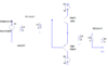
Hi, I designed a simple B-Amplifier.
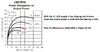
Output power across load= 3.91W
Power delivered by +15V DC = 6.35W
Power delivered by -15V DC = -6.35W
How should i calculate efficiency ?
Add both input Powers in formula ? or just use one ?
i.e.
Output/ Input power = (3.91Wx100)/6.35W or = 3.91Wx100/(6.35+6.35)W
Output power across load= 3.91W
Power delivered by +15V DC = 6.35W
Power delivered by -15V DC = -6.35W
How should i calculate efficiency ?
Add both input Powers in formula ? or just use one ?
i.e.
Output/ Input power = (3.91Wx100)/6.35W or = 3.91Wx100/(6.35+6.35)W
Attachments

Last edited: