mnkjoi
New Member
Hey ,
Could someone helps me please with this :
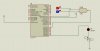
Write a program that will check the input of 2-input quadruple NAND , if the NAND gate works properly then the LED connected to RD6 should be ON , otherwise the LED should be ON . Assume PORTC connected to the inputs of quadruple 2-input NAND gates , two LEDs connected to most two bits of PORTD .
Using pic assembly language .
Could someone helps me please with this :
Write a program that will check the input of 2-input quadruple NAND , if the NAND gate works properly then the LED connected to RD6 should be ON , otherwise the LED should be ON . Assume PORTC connected to the inputs of quadruple 2-input NAND gates , two LEDs connected to most two bits of PORTD .
Using pic assembly language .

") .
.