Continue to Site

Welcome to our site!

Electro Tech is an online community (with over 170,000 members) who enjoy talking about and building electronic circuits, projects and gadgets. To participate you need to register. Registration is free. Click here to register now.

  • Welcome to our site! Electro Tech is an online community (with over 170,000 members) who enjoy talking about and building electronic circuits, projects and gadgets. To participate you need to register. Registration is free. Click here to register now.

Confused (about electronic circuits)

Status
Not open for further replies.

jonthornham

New Member
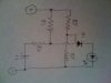
I recently started learning about electronic circuits. I am working through the book "Make Electronics" by Charles Platt. I am changing things as I go to try and understand what happens when I make changes. However I am lost with what happens when I try the following. My circuit is in the picture attached.

**broken link removed**

The components are:
R1: 470,000Ω
R2: 220Ω
R3: 220Ω
R4: Variable (here's where I get confused)
C1: 22µF
Q1: 2N6027 PUT
Diode

So basically the the capacitor charges until the voltage on the anode of the PUT is greater than the gate value. At this time current is discharged from the capacitor into the anode out of the cathode and the LED lights up.

My confusion comes when I change the value of R4. My thought is that if I were to increase the value of R4 the LED would flash less frequently and for a longer period of time. However when I increase R4 in flashes more frequently and I have no idea why.

Can someone please help?

Take care,

Jon
 
Last edited:
R1/R4 make a voltage divider that splits the voltage between the supply and C1 voltage. As R4 is the lower leg, the gate will reach the threshold earlier. Try changing R1 instead and you should see the desired results. BTW, I think you have the gate and anode reversed.

A tip so you get quicker responses, when drawing diagrams follow simple rules,
1. Power (+) is the top line.
2. Gnd (-) is the bottom line.
3. Supply is on the left.
4. Try to keep components in the direction of current flow. (R1, R4 & C1 vertical and SCR pointing down)

Following these simple rules will enable people to understand your diagram in seconds and make them more likely to respond. To understand your diagram, I had to rotate and flip it - see attached.

Mike.
 

Attachments

  • scematic.jpg
    scematic.jpg
    80 KB · Views: 294
Last edited:
Probably. Intuatively, think of R1 and R4 as a voltage divider and pretend the cap is a short circuit. making R4 bigger is lowing the voltage on the anode.
 
Confused

Sorry,

Still not getting it. Let me explain what I see and maybe you can correct my thinking.

I understand that if I apply the voltage divider rule the voltage on the anode is less if R4 is greater. Since the gate establishes the the threshold point when current starts to flow and R2 and R3 do not change the threshold remains the same. Now if I start with a 100Ω resistor at R4 the capacitor will charge at a certain rate and once the combined voltage from the supply and capacitor exceed the threshold set by the voltage at the gate the capacitor will discharge though R4, through the anode, through the cathode until the voltage returns to a value less than the threshold set by the gate. At this time the gate acts a a resistor again until the steps above are repeated.

Now if I increase R4 to 680Ω the voltage at the anode is less due to the voltage divider rule. The threshold at the gate however is the same. In my mind I have more voltage I need to make up with the capacitor because the voltage at the anode from the supply is less than when R4 was 100Ω because of the voltage divider rule. Now since R4 is greater the capacitor will charge slower due to the time constant τ = RC. This in my mind seems like it would take longer to accumulate the required voltage at the anode to overcome the threshold set at the gate. This in turn would make the LED blink slower. However it doesn't. Obviously I am missing something. Maybe where the current comes from when the voltage at the anode exceeds the threshold at the gate. Does the current come from the supply, capacitor or both?

Thanks,

Jon
 
R2 and R3 make a voltage divider.

When R2s resistance increases, there is less voltage on the PUT gate.
Then the capacitor charges up, but not all the way, the PUT will fire quicker.

When R2s resistance decreases, there is more voltage on the PUT gate.
Therefore, the capicitor will have to charge almost all the way up to get the PUT to fire.

Does that work with the circuit?

Never mind this but this should change flash rate too
 
Last edited:
The capacitor draws current through R1 and R4 because it is charging up.

Less capacitor charge current goes through R4 when its value is increased, so the voltage drop on R1 is less. Hence the PUT fires quicker.

More capacitor charge current goes through R4 when its value is decreased, so the voltage drop on R1 is greater, so the PUT fires less often.

The voltage at the PUT anode changes with the charge current that goes through R1.
When more current -which is changed by R4- goes through R1, the voltage drop across R1 increases.
When less current -which is changed by R4- goes through R1, the voltage drop across R1 decreases.

Got it?
 
Last edited:
Status
Not open for further replies.

Latest threads

New Articles From Microcontroller Tips

Back
Top