Continue to Site

Welcome to our site!

Electro Tech is an online community (with over 170,000 members) who enjoy talking about and building electronic circuits, projects and gadgets. To participate you need to register. Registration is free. Click here to register now.

  • Welcome to our site! Electro Tech is an online community (with over 170,000 members) who enjoy talking about and building electronic circuits, projects and gadgets. To participate you need to register. Registration is free. Click here to register now.

configuration setting?

Status
Not open for further replies.

haowhaow

New Member
im newbie in programming.....
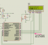
im using hi tech compiler, pic18f4520 and 16 x 2 lcd.....
after simulation is ok....but in real device, my lcd is blank .....
i dunno how to configure my code.....can anyone here helps me to solve it??


here is my code:

Code:
#include <htc.h>
#include <math.h>


#include "lcd.h"
__CONFIG(1, FCMDIS & IESODIS & HS);
__CONFIG(2, BORDIS & BORV45 & PWRTEN & WDTDIS & WDTPS1);
__CONFIG(3, CCP2RB3 & LPT1DIS & MCLRDIS & 0xFDFF);
__CONFIG(4, DEBUGDIS & XINSTDIS & LVPDIS & STVRDIS);


//Simple Delay Routine
void Wait(unsigned int delay)
{
for(;delay;delay--)
__delay_us(100);
}
void ADCInit(void){
ADCON0=0b00000001;	// select Fosc/2
ADCON1=0b00001110;	// select left justify result. A/D port configuration 0
ADCON2=0b00001010;
}
unsigned char read_adc(unsigned char ){
ADON = 1;	// initiate conversion on the selected channel
GODONE=1 ;//Start conversion
while(GODONE= 1)continue;
return(ADRESH);	// return 8 MSB of the result
}
void main()
{
//Let the LCD Module start up
Wait(100);

//Initialize the LCD Module
LCDInit(LS_BLINK);

//Initialize the ADC Module
ADCInit();

//Clear the Module
LCDClear();

//Write a string at current cursor pos
LCDWriteString("Temperature:");
LCDWriteStringXY(5,1,"Degree C");


while(1)
{
unsigned int val;
unsigned int t;	 //Temperature

val=read_adc(); //Read Channel 0

t=round(((val*5000)/1024)/10);

LCDWriteIntXY(0,1,t,3);//Prit IT!


Wait(1000);

}	
}
 

Attachments

  • 1.JPG
    1.JPG
    137.2 KB · Views: 221
Last edited by a moderator:
Post your LCD.h file

my LCD.H file as shown

Code:
#include <htc.h>

#define _XTAL_FREQ 20000000UL

#include "myutils.h"


#ifndef _LCD_H
#define _LCD_H

#define FOURBIT_MODE    0x0
#define EIGHTBIT_MODE    0x1

typedef unsigned char uint8_t;

/*_________________________________________________________________________________________*/

/************************************************
    LCD CONNECTIONS
*************************************************/

#define LCD_DATA D    //Port PD0-PD3 are connected to D4-D7

#define LCD_E D     //Enable/strobe signal
#define LCD_E_POS    4    //Position of enable in above port

#define LCD_RS B    
#define LCD_RS_POS 1

#define LCD_RW B
#define LCD_RW_POS 2


//************************************************

#define LS_BLINK 0B00000001
#define LS_ULINE 0B00000010


/***************************************************
            F U N C T I O N S
****************************************************/

void LCDInit(uint8_t style);
void LCDWriteString(const char *msg);
void LCDWriteInt(int val,unsigned int field_length);
void LCDGotoXY(uint8_t x,uint8_t y);

//Low level
void LCDByte(uint8_t,uint8_t);
#define LCDCmd(c) (LCDByte(c,0))
#define LCDData(d) (LCDByte(d,1))

void LCDBusyLoop();


/***************************************************
            F U N C T I O N S     E N D
****************************************************/


/***************************************************
    M A C R O S
***************************************************/
#define LCDClear() LCDCmd(0b00000001)
#define LCDHome() LCDCmd(0b00000010)

#define LCDWriteStringXY(x,y,msg) {\
 LCDGotoXY(x,y);\
 LCDWriteString(msg);\
}

#define LCDWriteIntXY(x,y,val,fl) {\
 LCDGotoXY(x,y);\
 LCDWriteInt(val,fl);\
}
/***************************************************/


/*_________________________________________________________________________________________*/
#endif
 
Last edited by a moderator:
haowhaow the way the LCD module works with Hi-tech you can't use E on PORTD.
It writes the lcd data as one byte to PORTD and then shifts it for 4 bit mode
 

Attachments

  • Hi_lcd.PNG
    Hi_lcd.PNG
    170.9 KB · Views: 192
haowhaow take a look at this your doing something wrong with the Library Files

There no way your code will work on a real chip I think your loading a ISIS sample and changing it.
It will let you but that don't mean it works. I only have the demo and I don't think to much of it.

This code will work just change for your chip I did it on a 18f4550 it will work on the 18f4520 too. Just change for that chip.
 

Attachments

  • hi-teck_adc.zip
    155 KB · Views: 158
Last edited:
haowhaow take a look at this your doing something wrong with the Library Files

There no way your code will work on a real chip I think your loading a ISIS sample and changing it.
It will let you but that don't mean it works. I only have the demo and I don't think to much of it.

This code will work just change for your chip I did it on a 18f4550 it will work on the 18f4520 too. Just change for that chip.

in the lcd.h file
#define LCD_DATA LATD
#define LCD_DATA_PORT PORTD
what it mean??
how to connect lcd data with port D?
lcd_d0 with LATD0??
lcd_d1 with LATD1??
lcd_d2 with LATD2?? and so on???
 
No you have data on PORTD 0 to 3 and E, RS, RW on say PORTB

Here a better look
 

Attachments

  • lowerPORT.PNG
    lowerPORT.PNG
    18 KB · Views: 189
Last edited:
Status
Not open for further replies.

Latest threads

New Articles From Microcontroller Tips

Back
Top