Continue to Site

Welcome to our site!

Electro Tech is an online community (with over 170,000 members) who enjoy talking about and building electronic circuits, projects and gadgets. To participate you need to register. Registration is free. Click here to register now.

  • Welcome to our site! Electro Tech is an online community (with over 170,000 members) who enjoy talking about and building electronic circuits, projects and gadgets. To participate you need to register. Registration is free. Click here to register now.

Computer Fans

Status
Not open for further replies.
This may work for a 2 speed setup. (6volt-12volt)
Somebody else check it though, Ive been up all nite....tired :?
 

Attachments

  • 2_speed_fan_switch2.jpg
    2_speed_fan_switch2.jpg
    8.6 KB · Views: 675
Try using only one or two fans - that should help a lot with the heat problem. If you use computer fans, they are designed to run at a fixed speed and not be adjustable. The fan keeps its own motor cool when running at the rated speed. A single diode will reduce the current going to the motors but I wouldn't recommend messing with the fans. I would be surprised if the fan noise can even be heard with your amp cranked - they are really quiet. While the fan(s) will pull the heat out, I was wondering about an amp that can't handle its own heat...I hope you don't have an amp problem.
 
Thanks seeker for the diagram, it works fine. Very simple too. Ive been messing around in croc clips for a while and come up with something, it looks rank compared to yours but Id like to have more control over what goes on :wink: .

(Is it just me that likes everything to have loads of buttons and look like a flight panel from a fighter plane :lol: :lol: , or perhaps its a male thing?? :lol: )

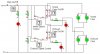
There is one problem with my circuit, when its changed to 6V the motors dont work, I think basically croc clips is giving the motors a resistance of zero so its used across the resistor in the potential divider. What would happen if I did this for real? If it would be like that could anyone tell me how to fix it?
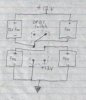
Basically I want,
-Main on/off
-Intake on/off
-Intake speed
-Exhaust on/off
-Exhaust speed

Gene, I think my amps alright for the heat, its just because I have my cd and radio decks on top of it so there isnt much room at all for heat to escape. Also its the summer holiday and Im bored so I thought Id make a little project :lol: .

Wow big post :shock: ,
Thanks again,
Lizo.
 

Attachments

  • fan_control.JPG
    fan_control.JPG
    33 KB · Views: 674
hey lizo, Your project is snowballing big time! But im sure the final product will kick ass! I'm not to sure on fan speed control but... My Volcano 7+ heatsink is a varible speed. Could be specially designed fan motor though.
 
Lizo...dude....you're turning this into rocket science :shock:

I think I see what you're doing but a few corrections imho:

the 5k resistors are wrong...the fans will not run with that. Try 40 ohm

On the bottom 5k (change to 40 ohm) run it directly to the 12 volt line.

I think this will give you about 6 volts low and 12 volts high. the rest of your bells and whistles looks good tho :D
Still sleepy .....must find cool dark place to ...zzzzzzzz
And break the connection between the 2 5k resistors as denoted by the "X'"
 

Attachments

  • mod.fan_control2.jpg
    mod.fan_control2.jpg
    16.8 KB · Views: 641
Yeh sorry about this seeker lol :wink: .

I tried what you said and the resistors blew up hehe, says power rating is 2W and it was 3.3W, I fiddled with it and anything below 70ohms resulted in them blowing up. When they are 70ohms the voltage is dropped right down to 1.47V and that isnt anywhere near enough to drive the fans. Also I had to break the connection below the bottom resistor to the 0V rail.

Im gonna fiddle around with it and see what happens, will I need to put any diodes in because of the motors?

Thanks for your time.

Lol Lewis get some watercooling :lol: .
 
WAIT! STOP! I'm wrong about the bottom resistor :x
"X" still denotes no connection
 

Attachments

  • mod.fan_control00001corrected.jpg
    mod.fan_control00001corrected.jpg
    10.1 KB · Views: 635
No lizo, I don't see any need for diodes at all.... also I don't see how any resistors could burn with my (sleepy) schematic.
What kind of fans do you have? what are the voltage/ current/ wattage ratings on them? I'll send you replacement parts for free if my schematic
as posted burned up anything :oops: serious
 
Lol seeker dont worry about things blowing up, croc clips is a simulation program they blew up on my screen :p . I havent bought the fans yet but I think they are 12V, 0.26A fans, not sure on the wattage.
 

Attachments

  • bang.JPG
    bang.JPG
    1.7 KB · Views: 384
You need fairly large wattage resistors if you are going to limit current....
I thought you understood the ohm's law thing there. I apologise.
 
Lizo, scared me.....felt bad and stuff. Fans that run at 12 volts and consume .26 amps would be dissipating about 3.12 watts. Without going into the math too much you would need a 23 ohm resistor in series with 1 fan to drop the voltage to 6 volts (slow and quiet) I'm thinking that it comes out to a little over 2 watts per resistor per fan.

Going back to your schematic I see a switching setup for 2 speeds with indicator lights and the option for turning on and off intake/output fans.
Myself, if the amp needed cooling I would turn on either 6 or 12 volts.

No offense at all, but to me it looks like you are making it way too complicated.
If you have fans over the intake and output keep in mind that fans that are not energised are blocking air flow. Therefore I would always have them running at 6 volts at least.....your amp will love you for that :lol:

If you want I could add on a LED circuit for hi and low but I'm pretty sure you could do that for yourself

(36 hours and counting, neeeed sleeeeep)

anyone else feel free to jump in here if I'm wrong
 
Sorry for making you feel bad, I should have let you know that it was a simulation.

No offense taken, its just me and my flight panels :p I think ill just go back to your original idea with the DPDT switch as that was incredibly simple. I can always change it later on. I never really took in to account of the fans being off and blocking the airflow.

Thanks for everyones help, and sorry for dragging this on for ages.

Lizo.
 
Status
Not open for further replies.

Latest threads

New Articles From Microcontroller Tips

Back
Top