Continue to Site

Welcome to our site!

Electro Tech is an online community (with over 170,000 members) who enjoy talking about and building electronic circuits, projects and gadgets. To participate you need to register. Registration is free. Click here to register now.

  • Welcome to our site! Electro Tech is an online community (with over 170,000 members) who enjoy talking about and building electronic circuits, projects and gadgets. To participate you need to register. Registration is free. Click here to register now.

Computer controlled Hotwire cutter (heat card fault)

Status
Not open for further replies.

foamworx

New Member
Hi all
Looking for a little help please....
I run large ncn industrial type polystyrene computer Hotwire cutters .
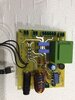
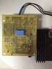
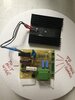
I have a major problem with my card that seems to control the heat running to my heat wire on the machine.
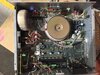
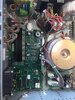
It runs off the motherboard which has X-Y 2 axis which works fine we just can’t get the heat to happen .
Does not blow fuses when we turn it on or off.
The company the makes the machines does not make this board no more and won’t provide a circuit diagram for it ....
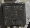
Any thoughts on what components on this board what could be causing the problems wh
The controller box that runs the machine is over 10 years old.
Any help would be greatly appreciated....
Cheers
Phil
 

Attachments

  • 728DB0F4-C4EC-4BD6-A615-CAFADDCC7D76.jpeg
    728DB0F4-C4EC-4BD6-A615-CAFADDCC7D76.jpeg
    845.1 KB · Views: 216
I'm guessing ncn is a typo and should be cnc. Looks like your board is a constant current source to feed the hot wire. Most likely failed component is the 3 pin black device on the left - probably a mosfet. Do any components have numbers on them?

Mike.
Edit, with no foam in place, does everything move as expected and it's just the wire not getting hot?
 
Hi Mike
Sorry yes large CNC type computer controlled hot wire cutter .
Yes everything else works fine ....
We are just waiting for a triac ( black)three pin component to start replacing that 1st
The blue rectangular component is a reed relay which we are waiting on as well they are on back order and won’t be in store for a couple more weeks.
 
They don’t make this one anymore more but we have found one with the same values and specs
 

Attachments

  • C0888041-8EC6-46CF-B598-77900E680DE3.jpeg
    C0888041-8EC6-46CF-B598-77900E680DE3.jpeg
    166.2 KB · Views: 182
Reed switch ..... this is also not made anymore but we have found another one with the same values and specs....
Just hoping this could be the problems but we are asking for any input and advise.
Cheers
Phil
 

Attachments

  • B0ECDBE4-8B94-4333-8D47-47285C06C3F2.jpeg
    B0ECDBE4-8B94-4333-8D47-47285C06C3F2.jpeg
    189.9 KB · Views: 175
This is a pic of the inside of the controller box to give people a bit of an idea.
It runs a wire 2.5 m long .
 

Attachments

  • 4221B3FB-4C34-4DBA-9F70-EBACADEE5B7E.jpeg
    4221B3FB-4C34-4DBA-9F70-EBACADEE5B7E.jpeg
    1.6 MB · Views: 193
  • A5975F1F-ED4E-42BE-BA10-EF13054DC2CC.jpeg
    A5975F1F-ED4E-42BE-BA10-EF13054DC2CC.jpeg
    1.2 MB · Views: 183
Can you post a picture of the underside of the board ? What connects to all of the connectors on the board ? I assume the green item is a transformer but I don't think it is large enough to supply the current through the cutting wire so I imagine there is a high current low voltage supply to the board and probably mains voltage to the primary of the transformer. Is the current through the wire controlled manually or is it computer controlled so the current is increased as the speed of movement of the wire through foam is increased ? If you have any schematics they would probably be helpful. I think it is unlikely to be the triac causing they fault as they tend to fail short circuit.

Les.
 
Hi Les
Thanks for your reply
The machine is all computer controlled temp is always the same .
Yes a circuit what be great but the company won’t supply one to me even though they don’t make that heat card anymore.
I will take a pic of the underside tomorrow and post it .
 
Hi Les
Here’s a couple me pics
 

Attachments

  • 3149EC0D-A317-4ACC-87E0-FE1FB5D4FB70.jpeg
    3149EC0D-A317-4ACC-87E0-FE1FB5D4FB70.jpeg
    901.5 KB · Views: 197
  • 48B3D077-3AF0-4BC1-B3E1-B850F5772302.jpeg
    48B3D077-3AF0-4BC1-B3E1-B850F5772302.jpeg
    942.3 KB · Views: 194
I've not been able to trace out much of the schematic as many of the tracks are hidden by components. It would be easier for someone that had access to the board to follow the track using continuity checks. I have cropped your pictures and mirrored the etch side to make it easier to follow the tracks.
100121etch_b.jpg

100121com0_b.jpg


I have established a few bits of information that may be of help. Calling the sockets on the right hand side of the board starting from the top A, B. C, D and counting the pins on the sockets from the top. I think socket A is the drive to the relay coil Pin 1 - Pin 2 + I think socket B is the power source for the cutting wire. (Probably low voltage AC) Socket C pins 3 (-) and 4 (+) is a DC output derived from the transformer and the bridge rectifier to the left of the transformer. Socket D is the AC input to the board and is probably 110 volts as the two primaries on the transformer are connected in parallel. You can probably confirm this from the markings on the side of the transformer. The right hand diode of the group of 5 diodes is just a back EMF protection diode across the relay coil. The other 4 diodes form another bridge rectifier. These following comments are just guesswork. The mains input to socket D and the low voltage AC to socket B are on permanently. The low voltage relay drive is only present when the heating wire needs to be powered.
I hope this information is of some help with tracing the fault.

Les.
 
Last edited:
Status
Not open for further replies.

Latest threads

New Articles From Microcontroller Tips

Back
Top