Continue to Site

Welcome to our site!

Electro Tech is an online community (with over 170,000 members) who enjoy talking about and building electronic circuits, projects and gadgets. To participate you need to register. Registration is free. Click here to register now.

  • Welcome to our site! Electro Tech is an online community (with over 170,000 members) who enjoy talking about and building electronic circuits, projects and gadgets. To participate you need to register. Registration is free. Click here to register now.

Composite Video Signal Amplifier

Status
Not open for further replies.

ThatITGuy

New Member
I will be installing some cameras and one of the cable runs will be longer than the signal can reach. I looked around for amplifiers to buy, however they are much more expensive than I am willing to pay.

After quite a bit of looking around online, I found the AD828 Video Op-Amp which appears to provide a simple means of amplifying a video signal. The datasheet has schematic examples that seem usable, but do not operate with the proper voltage (I would like 12v so it can run off the camera's power supply).

I need to know if this circuit would do what I need, and what changes would need to be made to make it work with 12 volts.

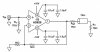
I have attached the schematic I would like to use from the bottom of page 11 in the AD828 datasheet.
 

Attachments

  • screenshot.01.jpg
    screenshot.01.jpg
    35.5 KB · Views: 1,119
Last edited:
You said you were installing cameras.... more than one. Take the 12V from TWO cams, connect them together, so you have +12V, -12V, then you can connect this to your circuit.
 
Last edited:
I am kind of confused as far as positive/negative voltages and single/dual power supplies.

If I have this share a power supply with 1 camera, I would have +12 and -12. What becomes ground? Would common point not connected to either +12 or -12 be considered 'ground'? [I know this is some pretty basic stuff, but I was taught 'ground' is a common connection to a singe side of the power source (usually negative)]
 
If the 12 outputs on your cameras are generated independently, you can connect the supplies lik this:

Camera 1 +12V-------------------- +12V
Camera 1 ground --|

Camera2 +12V ---|
Camera2 ground ------------------- -12V

crutschow thinks your 12V power supplies are NOT independent. I don't know why he thinks that, but we need to make sure this are independent before connecting them this way. Can you provide information about how your cameras are connected? What produces the 12V?

EDIT: The final appearance of this post does not look correct, as it does in the text entry window. Camera1 ground should be shown connected to camera2 +12V. Ground in this system then becomes the connection of Cam1 ground and Cam2 +12V
 
Last edited:
How do you know they have a common ground?
Because it's quite likely the video common is connected to the power supply common, and since the video commons between the two cameras will be tied together via the coax, than the power supply commons will also be tied together.
 
The video amplifier does not amplify anything. Its gain is 1 like a piece of wire.It has a 75 ohm input impedance and it can drive a load of 75 ohms, just like a piece of wire.What is wrong with the long cable run? If the source has a 75 ohm impedance, the cable has a 75 ohm impedance and the load has a 75 ohm impedance then a fairly long cable will be able to be used without an amplifier.
 
The amp's voltage gain is 2. That's knocked back down by the output resistor. The feedback resistor need to increase for an overall gain greater than 1.
 
Last edited:
Status
Not open for further replies.

Latest threads

New Articles From Microcontroller Tips

Back
Top