Continue to Site

Welcome to our site!

Electro Tech is an online community (with over 170,000 members) who enjoy talking about and building electronic circuits, projects and gadgets. To participate you need to register. Registration is free. Click here to register now.

  • Welcome to our site! Electro Tech is an online community (with over 170,000 members) who enjoy talking about and building electronic circuits, projects and gadgets. To participate you need to register. Registration is free. Click here to register now.

components for this circuit i've come up with for a bike alarm

Status
Not open for further replies.

Ben_Taylor

New Member
Hello,
I'm planning on making a simple bike alarm for use overnight in a tent, which will consist of simple components from www.maplin.co.uk and the alarm will be activated if a wire, which will go round the bike and the other end round my wrist while i'm asleep, is broken.

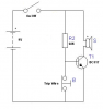
Thus I think the following circuit should suffice?
**broken link removed**

Basically,
"S" is going to be this: **broken link removed** (it apparently 'draws 90ma' so I'm presuming it has its own internal resistor which is why I haven't included one on the emittor)
"W" is going to be the wires that will run round the bike

What I would like to ask from you guys is firstly is does the circuit look ok, and what should the values of R1 and R2 be, and what type of transistor "T" should I use?
 
Well, normally when the alarm is armed but not triggered W and B would be allowing current to flow through R2 and not through the base of the transistor, but when 'W' is broken, current flows through the base of the transistor - causing it to conduct, and the siren to be activated. Doesn't it??
Please tell me where I've gone wrong if you don't think that'll work...if you wouldn't mind?

Thanks
 
R2 drains the battery all the time the alarm is not blasting.
 
If you rearrange the components a bit, it'll work:
 

Attachments

  • bikealarmcircuit.PNG
    bikealarmcircuit.PNG
    18.8 KB · Views: 136
Here's another version, but w/o the switch. The transistor will leak very little current and the switch probably won't be needed. All right, I forgot to add it.:D
 

Attachments

  • bike alarm.JPG
    bike alarm.JPG
    75.6 KB · Views: 141
Here's another version, but w/o the switch.
Yes, but your circuit draws 9mA idle current while mine draws only 0.13mA. The battery will last 68 times longer in standby with my circuit. I used the BC517 because it is a darlington and available at Maplin, allowing me to use a 68KΩ resistor and still have it saturate.
For even lower current, a FET could have been used, but ESD may have become a problem for a noob.
 
Last edited:
Yes, but your circuit draws 9mA idle current while mine draws only 0.13mA. The battery will last 69 times longer in standby with my circuit. I used the BC517 because it is a darlington and available at Maplin, allowing me to use a 68KΩ resistor and still have it saturate.
For even lower current, a FET could have been used, but ESD may have become a problem for a noob.

Crap!!! I knew I'd get slammed on that circuit (I didn't take the "sleep-mode" current draw into consideration.). How about using the BC51X PNP variety in my circuit? Thanks for pointing that out.
 
Crap!!! I knew I'd get slammed on that circuit
Didn't intend to slam. :D Just pointing out a slight design flaw. ;)
How about using the BC51X PNP variety in my circuit?
Yes, the BC516 would work in your circuit, letting you change the 1K to a 68K. Some people feel more comfortable switching the + side, though it really makes no difference in this case.
 
We didn't slam him. We just posted the same criticism of his circuit at exactly the same time.
 
Ahhh, Here is another (low tech) solution...
Since that wire is attached to both the bike and your wrist, why not delete the alarm altogether (save some weight) and depend on the pull of the wire on your wrist to awaken you?
**broken link removed**
 
Last edited:
We didn't slam him. We just posted the same criticism of his circuit at exactly the same time.

I was kidding. I have a bad habit of forgetting the "big grin". It's hard to convey humor w/o visual stimuli sometimes.
 
R2 drains the battery all the time the alarm is not blasting.

Does it - what even if R2 is really big?

If you rearrange the components a bit, it'll work:

aha - ok, thanks! I don't really get that circuit though - how is it that the battery doesn't drain through R2 when the circuit through the trip wire is made and the switch is on - but it does with mine?

edit: I can see how your circuit draws 0.13mA idle current - 9/68000 = 0.000013. But if i make R2 in my original circuit 68k, how will it draw any more current - is it because current will leak through the transistor?
 
Last edited:
Does it - what even if R2 is really big?


aha - ok, thanks! I don't really get that circuit though - how is it that the battery doesn't drain through R2 when the circuit through the trip wire is made and the switch is on - but it does with mine?

edit: I can see how your circuit draws 0.13mA idle current - 9/68000 = 0.000013. But if i make R2 in my original circuit 68k, how will it draw any more current - is it because current will leak through the transistor?

Like I said before, your original circuit does nothing, the transistor isn't connected in any way to the switches.
 
Does it - what even if R2 is really big?


aha - ok, thanks! I don't really get that circuit though - how is it that the battery doesn't drain through R2 when the circuit through the trip wire is made and the switch is on - but it does with mine?

edit: I can see how your circuit draws 0.13mA idle current - 9/68000 = 0.000013. But if i make R2 in my original circuit 68k, how will it draw any more current - is it because current will leak through the transistor?

If you substitue the 2n3906 with the transistor in kchristes circuit (except it would be the PNP variety), and a 68KO in place of the 1KO, it'll work. R2 does draw excessive current from the battery because of the smaller resistance and the higher base current required to saturate Q1 (Woops:eek:).
 
Status
Not open for further replies.

Latest threads

Back
Top