Continue to Site

Welcome to our site!

Electro Tech is an online community (with over 170,000 members) who enjoy talking about and building electronic circuits, projects and gadgets. To participate you need to register. Registration is free. Click here to register now.

  • Welcome to our site! Electro Tech is an online community (with over 170,000 members) who enjoy talking about and building electronic circuits, projects and gadgets. To participate you need to register. Registration is free. Click here to register now.

Component indentification

Status
Not open for further replies.

jkgr

New Member
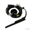
Hello, this is a small pcb from a transducer cabling from a raymarine dragonfly 4 pro fishfinder/gps. This small pcb is subpart of the transducer cabling and it is enclosed in a cylindrical rubber as you can see in the photo and it is located a few inches from the connector that you insert to the actual fishfinder. After an overvoltage issue i had on my boat i suspect that this component failed.
So, I would like to ask:

1) What is this component's purpose
2) How to test it
3) What happens if i try to bybass it completely
4)If you can help me find the same or an alternative

Thank you !
 

Attachments

  • 36669_6_n.jpg
    36669_6_n.jpg
    201.1 KB · Views: 135
  • a.jpg
    a.jpg
    652.7 KB · Views: 148
  • b.jpg
    b.jpg
    759.8 KB · Views: 131
  • c.jpg
    c.jpg
    741.5 KB · Views: 146
Last edited by a moderator:
It looks like a powerline filter, to stop noise from going to or comming from the transducer.
To make that fail theres a high chance that something else os blown too, as it would take a lot to damage a differential choke.
The unit might work without it, but the readings might well be well off.
 
The "WE" makes me think it is made by Würth Elektronik.
This picture is not right but is the surface mount newer version.
120084

Inside it looks like this:
120085
 
Measure the resistance from bottom left to bottom right wire or post. The resistance should be under 10 ohms probably under 2.
The top two pins should have the same resistance.
If one of the wires is "open" that is not good.
120086

There is a slim chance that the solder job under the part is bad. Try measuring from PCB pad to PCB pad (left to right).
 
I bet its fine, as the circuit path being just copper wire, its most likely if it was open that the thing would be charred to a crisp, uless you had a very high current spike which made the wire blow like a fuse, even then there'd be a skidmark of somesort.
I'd hazard a guess that 102 means 1000uH or 1mH.
 
I bet its fine, as the circuit path being just copper wire, its most likely if it was open that the thing would be charred to a crisp, uless you had a very high current spike which made the wire blow like a fuse, even then there'd be a skidmark of somesort.

Mostly that would be true, but 'occasionally' such coils are wound too tight, and the wire can fracture where it goes across a sharp corner - I've sometimes managed to repair such breaks, where it's accessible enough to tin each end of the wire and solder a small piece of wire across the break (or, if it's very accessible, run a new wire from the pin to the broken end).

But certainly such devices are EXTREMELY reliable, after all it's only a couple of pieces of thickish wire wound round a core.
 
Actually I get that on industrial contactors occasionally, I assumed it was bemf causing it to fail, maybe its as you say stresses weakening the wire during manufacture.
 
Status
Not open for further replies.

Latest threads

New Articles From Microcontroller Tips

Back
Top