Continue to Site

Welcome to our site!

Electro Tech is an online community (with over 170,000 members) who enjoy talking about and building electronic circuits, projects and gadgets. To participate you need to register. Registration is free. Click here to register now.

  • Welcome to our site! Electro Tech is an online community (with over 170,000 members) who enjoy talking about and building electronic circuits, projects and gadgets. To participate you need to register. Registration is free. Click here to register now.

Component Identification

Status
Not open for further replies.

Champ54

New Member
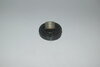
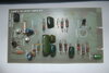
Hi Everyone. I am restoring a 1970's vintage automotive tune up machine and require some technical information regarding a component. It is marked ITT TS1201 72F . I think it may be a thyristor but I'm not sure. I contacted ITT but they were unable to assist. I think it may be an OEM special build which is why it is not shown in any publications. I would like to identify any possible way replacement for it. All assistance would be greatly appreciated. Thanks.
 
In-house numbers are commonplace, so there's probably no way to identify what it actually is - as such numbers are meaningless.

If you can find a schematic?, then you can probably work out what to use as a replacement - if not, drawing the circuit out should help in identification as well.

I'm presuming it's faulty? - have you tested it as a thyristor?.

Using alternative components isn't about finding an alternative for the component, it's about finding an alternative for the circuit.
 
Can you provide photos of the part and the PCB or machine section in which it is used?
 
Hi Nigel,
Thanks for the reply. Unfortunately I cannot locate a circuit diagram. I was planning to draw the circuit out as it does not seem to be very complicated. I've attached a couple of photos. As you can see someone has attached a capacitor on the back of the BC547(Q1001). The component I need to replace is QS1001.
The legs were completely rusted off so it is very difficult to test it. I soda blasted it to clean the rust off as there was no other way to do it. I tried chemical rust remover but it did nothing. Q1002 also appears to have been replaced as it is a BC557. I was hoping there might be enough of the legs left to allow me to solder on new ones but that is a very long shot that it would still work.
 

Attachments

  • Gen-Saw components.PNG
    Gen-Saw components.PNG
    30.8 KB · Views: 269
  • Gen-Saw (3).JPG
    Gen-Saw (3).JPG
    1.4 MB · Views: 272
  • TS1204 (2).JPG
    TS1204 (2).JPG
    799.6 KB · Views: 285
  • Gen-Saw (2).JPG
    Gen-Saw (2).JPG
    1.4 MB · Views: 285
As it says 'gen saw' on the board, does that mean it's a saw tooth wave generator?.

If so then it's quite possibly a uni-junction transistor, which were commonly used for such purposes (and which is 'similar' to a thyristor).

You can easily make a uni-junction transistor with an NPN and a PNP - like this:

 
You can also still get a 2N6027 (at least on ebay), which is a "Programmable unijunction" and should be able to work, if with some slight component changes.
 
You can also still get a 2N6027 (at least on ebay), which is a "Programmable unijunction" and should be able to work, if with some slight component changes.

Isn't a programmable one just the same as the normal one?, just with a fourth connection - to the NPN base on the diagram I linked to.
 
Hi Everyone,
Many thanks for the assistance I sincerely appreciate it. I think Nigel is correct about the circuit being a Saw Tooth Wave Generator. I have attached typical screen patterns that would be on the screen when the unit is connected to a running engine. The 2N2646 just might be the answer. As you may have gathered my electronics knowledge extends just about far enough to get me into trouble so I need all the help I can get. I'm actually a retired Civil Engineer but also have quals in automotive mechanics and automotive manufacturing as well. I have a 1974 Datsun 260Z I'm restoring and I want to use this machine to tune it. It is a very challenging project but I'm enjoying the processes involved in the research and the restoration.
Best Regards, Barry
 

Attachments

  • Screen Pattern.jpg
    Screen Pattern.jpg
    7.9 KB · Views: 250
  • Secondary Pattern.png
    Secondary Pattern.png
    5.8 KB · Views: 245
Thanks everyone. I bought a 2N2646 from our local Jaycar store today that I intend to try out. It will be some time before I get the rest of the machine ready for test. It is actually a Repco 646 that was made in Australia by a Repco offshoot company called Replex Pty Ltd. They were an excellent tune up machine in their day. I would love to get it working again if I can. Great for the man cave as well.
 

Attachments

  • Repco 646.jpg
    Repco 646.jpg
    56.4 KB · Views: 269
I'm surprised the manual doesn't have, if not actual schematics, at least block diagrams indicating the various sub circuits.

It's been far too long since I worked on any of this stuff, but I suspect the board, as already mentioned, is the sawtooth generator for the screen (sweeps the trace across it).

QS1001 'may' be part of the retrace blanking circuit and could possibly be an SCR rather than a unijunction.

If it is an scr, a C106D1 (Cat # ZX7006 from Jaycar) would probably do the job with possibly a little bit of component value adjustment around it.
 
Hi, thanks for the suggestion. I have the user manual but it does not have any technical information only operator instructions. I have tried to google search for circuit information but have not been able to locate anything so far. I'm very interested in all possibilities. Any idea what other component adjustment may be required.?
 
Firstly, the circuit would need to be traced out to ascertain the components around it and then some idea of voltages on it.

Unfortunately, something of a chicken and egg situation without a manual

A service manual (from back then) probably would, but a user manual is unlikely to - as it's of no use to the end user.

Some early Sun stuff had both and then the later stuff just had a short description of the various blocks, so it varied by manufacturer.

Most of them these days won't even give you the time of day once you have parted with your money.
 
Firstly, the circuit would need to be traced out to ascertain the components around it and then some idea of voltages on it.

Unfortunately, something of a chicken and egg situation without a manual


Some early Sun stuff had both and then the later stuff just had a short description of the various blocks, so it varied by manufacturer.

The operative word been 'some' :D

It was highly unusual, and only a tiny amount of equipment ever did it.

Interestingly at one time it was normal for many European TV sets (UK sets never did) to include the circuit diagrams inside, such as Grundig etc. - perhaps one reason they never met UK safety standards?, bit of a fire hazard :D From an engineers point of view is was EXTREMELY helpful though :D
 
Hello again everyone. I have started drawing up the circuit for the Gen-Saw board and I will post it here as soon as its done. In the meantime here is a photo od the board with a bright light behind it so you can see the tracks. The CD106D1 sounds like it might have possibilities if I can find out what small adjustments ned to be made. Thanks again for all the assistance.
 

Attachments

  • Gen-Saw Circuit Board (4).JPG
    Gen-Saw Circuit Board (4).JPG
    1.5 MB · Views: 247
R1001, 1002, 1003 & 1004 are all the ones associated with the gate of the SCR (the G, A & C written on the pcb indicate it is now more likely to be an SCR).

First up would be to try it without changing any resistor values (but measure those resistors first to make sure they haven't drifted out of tolerance).

Those resistors are 5% tolerance, so if they measure more than 5% above or below their marked value - change them.
 
R1001, 1002, 1003 & 1004 are all the ones associated with the gate of the SCR (the G, A & C written on the pcb indicate it is now more likely to be an SCR).

Interesting there's no sign of those markings in the original pictures? - but assuming they are right, then it's a very useful indication, and particularly for which way the replacement should be fitted.
 
Thanks guys. The markings only showed up after I took the photo with a bright light behind it. I think Terry is correct. The markings would indicate that the original TS1201 was an SCR. The old resistors do look a bit the worse for wear so I was planning on changing them anyway.
 
Status
Not open for further replies.

Latest threads

New Articles From Microcontroller Tips

Back
Top