Continue to Site

Welcome to our site!

Electro Tech is an online community (with over 170,000 members) who enjoy talking about and building electronic circuits, projects and gadgets. To participate you need to register. Registration is free. Click here to register now.

  • Welcome to our site! Electro Tech is an online community (with over 170,000 members) who enjoy talking about and building electronic circuits, projects and gadgets. To participate you need to register. Registration is free. Click here to register now.

complex driving of LED matrix

Status
Not open for further replies.

justDIY

Active Member
I need some help figuring out the easiest / lowest parts count method of driving an LED array in a complex manner.

I would like to build an array that is 8 anode columns by 8 cathode rows. I need to have the array's "default" state ON rather than off. I need to be able to reverse bias each LED in the matrix. I need to be able to read the voltage stored by the junction capacitance of each LED in the matrix... I will read this voltage off the cathode side of the junction, with the anode side in a LOW state.

Right now I'm testing things with a 3x3 array... I have the anode columns driven by a 74HC595 serial shift register. I load the register with $FF, which sets the output state of each port to a logic HIGH or current source. The rows are directly attached to the tristate IO lines on my microcontroller. The default value for these ports is a logic LOW, which is the current sink.

Now the complex part. To 'read' my array, I shift a 0 across my column driver, setting a column into LOW state. Now I shift a 1 across the port in my microcontroller, briefly reverse-biasing the column that is set to a 0 state. Before switching to the next row, I set the current row's port to a HIGH-Z input state, and delay breifly, allowing the charge to transfer to the internal capacitors of the ADC module, reading the voltage stored in the LED. I then return the row to a logic LOW output, and proceed to the next row, repeating the process. Then I increment to the next column, and repeat the whole thing again. I'm using an interrupt driven routine to 'scan' the array at a very fast speed.

The problem I have is scalability. My hardware can handle the current demands of a 3x3 matrix, however, my 8x8 matrix will exceed the specifications of the 595 and my PIC. 8 leds at 20mA each requires 160 mA of current, to be sourced by the column driver and sunk by the row driver.

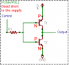
Here is the solution I've come up with for my anode column driver. I don't have the parts yet to test it...

**broken link removed**

I plan on using a P-Channel mosfet to provide the source current when the logic state is 1, with a diode to force the column to accept its current from the mosfet. When the logic state is 0, the mosfet will be non-conducting, and the diode should allow current to flow into the 595, acting as a current sink. The reverse bias current is very very tiny.

I am totally lost on what to do for the cathode row drivers. I know I could setup a similar mosfet 'gate?' to provide a good current sink, but how do I implement the high-z input mode.
 
A tiny detail - when you put a logic 0 on the gate of the P-channel MOSFET, it will turn ON, not OFF.
I don't understand how your circuit works. When you reverse bias an LED, the junction will charge to VCC volts. Do you zero the A/D input at the same time, so that when you go to tristate, you turn on the A/D input MUX so that some of the charge on the LED is allowed to flow into the A/D capacitance?
Have you considered that tristating involves switching two transistors off (pullup pchan, pulldown nchan)? I doubt that they will switch exactly simultaneously, which will result in some undesired net charge being transferred.
I don't want to rain on your parade, and I may totally misunderstand what you are doing, but I am afraid you will get results that do not entirely reflect what you are trying to measure.
 
Is it possible to show a schematic of the matrix you have so far?
you may get a better answer if you do.

It never hurts to add a resistor in series with your chain of LED's. This can help your 8x8 array to be within current limits.
 
Ron H said:
A tiny detail - when you put a logic 0 on the gate of the P-channel MOSFET, it will turn ON, not OFF.

ok, well that shoots that idea ... same effect using a PNP transistor... so, I can use two transistor, and invert my output on the shift register, on the anode side ... a 0 turns on the source transistor, a 1 turns on the sink transistor... maybe?

**broken link removed**

I don't understand how your circuit works. When you reverse bias an LED, the junction will charge to VCC volts. Do you zero the A/D input at the same time, so that when you go to tristate, you turn on the A/D input MUX so that some of the charge on the LED is allowed to flow into the A/D capacitance?

yes, the AD input is disconnected from the LED until after the reverse bias charging is complete, my program then switches the pin state from output-high to input-highz. next the AD is muxed onto the pin of the microcontroller connected to the LED cathode, the program pauses to allow the internal AD capacitor to charge, and then the pin is disconnected from the AD and the ad samples the charge in the capacitor... the steps involving connecting, sampling and disconnected the AD input is is all managed by the firmware inside the PIC (as far as I know), all I do is tell the mcu which AD channel I want to sample, and then tell it to start.

Have you considered that tristating involves switching two transistors off (pullup pchan, pulldown nchan)? I doubt that they will switch exactly simultaneously, which will result in some undesired net charge being transferred.

I understand there may be some nanoseconds delay between the switching from push to pull but the time is not enough to effect the readings I am taking. I can see them on my scope, faintly appearing as 'noise'.

I don't want to rain on your parade, and I may totally misunderstand what you are doing, but I am afraid you will get results that do not entirely reflect what you are trying to measure.

Here is the background on what I'm working on ... basically I am using the photovoltaic properties of LEDs to build an active sensor array, where the LEDs appear to be 'on' but are actually alternating between a state of emitting light and a state of detecting light. Using light reflected from nearby leds, which are on at the time of sampling, I'm able to generate 3D positional data of an object interacting with the array.

The problem I'm having is scalability. To get a good resolution, I need a large array... to get a large array in a cost effective manner, I have to find a way to drive a LOT of leds with a single microcontroller.

The biggest hangup is how to interface the cathode rows with the microcontroller, but retain the ability of the microcontroller to 'sense' the row.

Here is the basic idea of how I have things setup now:

**broken link removed**
 
I would like to build an array that is 8 anode columns by 8 cathode rows. I need to have the array's "default" state ON rather than off. I need to be able to reverse bias each LED in the matrix. I need to be able to read the voltage stored by the junction capacitance of each LED in the matrix... I will read this voltage off the cathode side of the junction, with the anode side in a LOW state.
Reading the voltage can be difficult, especially when your circuit is digital.
However, reading the LED state (on or off) isn't. I don't understand why you need to reverse-bias LED's.

You need to be aware that a LED lights up when anode is connected to +ve and cathode is connected to -ve through a resistor.

your push-pull configuration can become part of an amplifier by adding a resistor between base and collector of transistor T1. This also defaults your input to a logic 1 because the resistor is tied to +ve.
 
mstechca said:
Reading the voltage can be difficult, especially when your circuit is digital.
However, reading the LED state (on or off) isn't. I don't understand why you need to reverse-bias LED's.

Well, in my previous setups, where each LED was discretely controlled by the microcontroller, there was no problem reading the leds. I haven't had time yet to actually connect my little array to the mcu, as I've been putting the 'cart before the horse', trying to figure out scalability before functionality.

I reverse bias the LED to place a charge across the P-N junction inside the LED. As light of a certain wavelength strikes the junction, this charge is diminished. This gives me a an analog 'light level meter'. Using a large number of these sensors in a group allows me to sense the 3-dimensional position of an object reflecting light into the array (most likely a finger tip). So, the reverse bias places a rougly 5v charge on the junction. Once I turn off the Vcc output on the microcontroller, and switch to a high impedance input, the charge begins to diminish.

In the case of RED leds, I have to allow approximately 500 uS delay for the charge to diminish sufficiently to be read, and equalize with the capacitance inside my ADC module. A bright reflection (say white paper or a mirrored surface), can diminish the voltage all the way down to the millivolt level. However, reflection from my fingertips usually results in a the voltage diminishing to the 1.2-2.3 volt range. LEDs receiving no reflected light remain at 3.2-3.5 volts.
 
Why can't you turn on one LED at a time - turn it on, reverse bias it, read the charge, go to the next LED, etc. ...
I'm sure you have thought of this. I'm just wondering why you can't do it. Is it a matter of taking too much time to scan a large array?
 
all the leds need to be on, unless I turn them off ... if I use multiplexers to scan through the LEDs one at a time (like a scrolling marquee sign does), there will be no light to reflect into the 'sensor', because the lights around it are all off (even though they appear to be on to the naked eye)

basiclly I need to re-create the PICs internal tristate abilities with heavier duty components, or find some sort of IC that does that already.

Does anyone know of a logic device with discrete tristate pins, rather than a global tristate (like the 595 and other multiplexors have)
 
this sounds like you are (eventually) trying to make a barcode scanner. Am I correct?
 
mstechca said:
this sounds like you are (eventually) trying to make a barcode scanner. Am I correct?
no, not a barcode scanner

here's the review:
justDIY said:
Here is the background on what I'm working on ... basically I am using the photovoltaic properties of LEDs to build an active sensor array, where the LEDs appear to be 'on' but are actually alternating between a state of emitting light and a state of detecting light. Using light reflected from nearby leds, which are on at the time of sampling, I'm able to generate 3D positional data of an object interacting with the array.

justDIY said:
Using a large number of these sensors in a group allows me to sense the 3-dimensional position of an object reflecting light into the array (most likely a finger tip). So, the reverse bias places a rougly 5v charge on the junction. Once I turn off the Vcc output on the microcontroller, and switch to a high impedance input, the charge begins to diminish.

as far as I know, there are only a tiny few scientists working on this technology world wide, so I guess I'm on my own... the few I contacted who are also doing this research have ignored my requests to share information.
 
How can LED's be light detectors?
I know they can be light emitter's, hence the name Light Emitting Diode

Also, I think there are photodiodes out there.
 
mstechca said:
How can LED's be light detectors?
I know they can be light emitter's, hence the name Light Emitting Diode

Eh Msechca,
I got the following quote from redrok, they are right into solar trackers

I have been looking for truly low cost and yet accurate conventional solar trackers. The CdS tracker is pretty good but lacks accuracy and sensitivity. I was thinking about using PV cells as the sensor. I was experimenting with LEDs and noticed they generate voltage in sunlight.
Bingo! This got me to thinking.

They generate quite a bit of voltage. The green ones generate about 1.65V, some as much a 1.74V. Not the piddley .55 volts of a silicon PV cell. How is this so? Well, it turns out green LEDs are made from Gallium Phosphide, a semiconductor with a much higher bandgap voltage.

So there you have it LED's can be used as light sensors

Cheers Bryan :D
 
how do I build what the 74HC125 offers, with discrete components?

it has four individual tri-state outputs ... so all I need to do is build a beefier version, which can sink more current.

https://www.electro-tech-online.com/custompdfs/2005/11/MM74HC125.pdf

I need to build an output stage that can offer a HIGH, a LOW and nothing at all

If I can get the "nothing" portion, then I can use something like a mux to connect the rows to a single analog input pin
 
mstechca said:
your push-pull configuration can become part of an amplifier by adding a resistor between base and collector of transistor T1.
The push-pull transistors won't work because their b-e junctions are forward biased and a dead short to the supply. Then the gain of the transistors will try to amplify the massive base current.
 

Attachments

  • pushpull.png
    pushpull.png
    5.3 KB · Views: 766
audioguru said:
The push-pull transistors won't work because their b-e junctions are forward biased and a dead short to the supply. Then the gain of the transistors will try to amplify the massive base current.

It's not a 'dead' short, it's 'only' two forward biased silicon junctions directly across the supply 8)
 
Nigel Goodwin said:
It's not a 'dead' short, it's 'only' two forward biased silicon junctions directly across the supply 8)
Since the transistors have current gain, the current will be higher than that therefore the supply and both transistors would be very dead. :lol:
 
why would you say its a dead short?

if the control signal is LOW, only the PNP transistor would be conducting, conversely if the control signal is HIGH, only the NPN transistor would be conducting?

That circuit is not of my design, I drew it based on numerous examples found on the 'net... not saying just because its on the net, it must be true... I also have it on a breadboard... the transistors are not smoking, they're not even warm, there is no short across my supply, as verified with my ammeter, the current draw is only that of the load connected (my leds)... the circuit is working as intended as far as I can tell.
 
...and multiposting, don't forget the multiposting.

Well, to back up what you said, I've also heard of complementing transistors in this back-to-back fashion, altough I've always seen it done with MOSFETs. As long as the load capacitance was kept very low, the circuit only shorted out for the few dozen ns to took for both devices to switch.
 
justDIY said:
why would you say its a dead short?

if the control signal is LOW, only the PNP transistor would be conducting, conversely if the control signal is HIGH, only the NPN transistor would be conducting?
Without a control signal input it has two 0.7V forward biased base-emitter junctions shorting the 5V supply down to 1.4V.
If your control signal had lots of current, and managed to go low enough to turn off the NPN then the supply voltage would be dragged down to about 1V through the forward biased base-emitter junction of the PNP.
Similarily, the control signal can't go high enough to turn off the PNP because it is clamped to 0.7V by the forward biased base-emitter junction of the NPN.

I also have it on a breadboard... the transistors are not smoking, they're not even warm, there is no short across my supply, as verified with my ammeter, the current draw is only that of the load connected (my leds)... the circuit is working as intended as far as I can tell.
Impossible. Maybe they are drawn incorrectly. Maybe they are emitter-followers like this:
 

Attachments

  • pushpull-wrong.png
    pushpull-wrong.png
    9.6 KB · Views: 428
Status
Not open for further replies.

New Articles From Microcontroller Tips

Back
Top