Continue to Site

Welcome to our site!

Electro Tech is an online community (with over 170,000 members) who enjoy talking about and building electronic circuits, projects and gadgets. To participate you need to register. Registration is free. Click here to register now.

  • Welcome to our site! Electro Tech is an online community (with over 170,000 members) who enjoy talking about and building electronic circuits, projects and gadgets. To participate you need to register. Registration is free. Click here to register now.

completely switching off a mosfet

Status
Not open for further replies.

Thunderchild

New Member
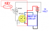
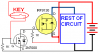
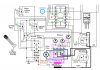
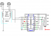
I'm using a IRF9540 in an automotive power control circuit, now the mosfet is feeding the field coil of a dynamo and due to working contraints I have to run this off the battery rather than the dynamo output so must make sue that when the vehicle engine has stopped i keep the mosfet completely switched off so as to not drain the battery, does it suffice to bring the gate to the same voltage as the source or does it need to go higher, I think realisticly I'm going to have problems here as any device i use to hold the gate to the source voltage will have a voltage drop
 
I have the same question for IRF9130 & IRF6215, I built a circuit for my buggy and at present, I have to turn it on and off, and I want to set it up so it turns on when key is on and off when the key is off and no power drain. I'm going to bench test it, but if someone KNOWS for sure already, let us know please.
kinarfi
 

Attachments

  • post.PNG
    post.PNG
    8.1 KB · Views: 615
Thunderchild,
The gate of a Mosfet draws zero DC current. It causes no DC voltage drop.
It needs smoething to discharge its fairly high gate capacitance for it to turn off quickly.

Kinarfi,
Your 2N7000 Mosfet is connected upside-down (drain and source are backwards).
The 2N7000 Mosfet has nothing to turn it off.
 
Hi audioguru,

what i'm saying is to ensure my p channel mosfet is completely off the gate should i beleive the at the same voltage as the source is not higher ? probably depends on the mosfet in question, if i use another transistor or an opamp output to take the gate to the source voltage which is also VCC surely the small voltage frop on the output (due to internal resistance of internal transistors) will mean that I can't truly pull the gate to the same voltage as the source unless i have a second supply.

in anycase I have resolved my problem another way but I'm still interested in the topic
 
A resistor from the gate to the source will completely turn off a Mosfet.
 
Kinarfi,
Your 2N7000 Mosfet is connected upside-down (drain and source are backwards).
The 2N7000 Mosfet has nothing to turn it off.

It's actually connected correctly, (unless I'm looking at the edited version) but the circuit is drawn so wierdly, that it's confusing. V+, B+, VCC and VDD should always be shown connected from the top of the diagram. V-, VSS and ground always shown connected at the bottom. Does need something to turn it off though.
 
Last edited:
Thanks, the first one never got edited, here it is redrawn with a resistor to turn off 2n7000, I just took what I had and deleted most of it and added what I needed, sorry for doing it wierdly.
Kinarfi
redrawn schematic, added 1 k resistor from the gate of 2n7000 to negative.

audioguru,
Judging by what you said earlier, I would guess that I need a resistor on each of these FETS also, correct?
Thanks
Kinarfi
 

Attachments

  • post.PNG
    post.PNG
    5.7 KB · Views: 362
  • post2.PNG
    post2.PNG
    27.8 KB · Views: 498
Last edited:
Earlier in this thread, it was said that I needed to discharge the FETs, in the attached drawing, do these FETs need to be discharged or are they discharged by the LM339? If I need to discharge them, would you make a suggestion please? If I put a resistor from gate to source, it also acts as load when the LM339 output is high and a series resistor with the pull up resistor when low, or is that backwards?
Thanks,
Kinarfi
 

Attachments

  • post.PNG
    post.PNG
    11.7 KB · Views: 305
You have the Source and the load's power supply for your Mosfets at the same voltage (-) so they won't do anything.

The mosfets need a fairly high current to quickly charge and discharge their gate capacitance but the "low power" LM339 comparator has a minimum output current of only 6mA.

The output of an LM339 comparator goes low when it is active. A resistor from the positive supply to the output (a pullup resistor) makes it go high.

OOP, Redrawn and corrected.
My TI data sheet says: and I did see the 6ma min
absolute maximum ratings
Supply voltage, VCC (see Note 1) . . . 36 V
Differential input voltage, VID (see Note 2) . ±36 V
Input voltage range, VI (either input). −0.3 V to 36 V
Output voltage, VO 36 V
Output current, IO 20 mA

Earlier in this thread, it was said that I needed to discharge the FETs, in the attached drawing, do these FETs need to be discharged or are they discharged by the LM339? If I need to discharge them, would you make a suggestion please? If I put a resistor from gate to source, it acts as load when the LM339 output is high and lowers the output voltage and as a parallel resistor to ground with the output when low, or is that backwards? As I analyze it, a resistor from gate to source in this case is useless.
Thanks,
Kinarfi
Edit
Using a 12 volt supply, I also need to lower my pull up resistors to 2K to have 6ma min current. Correct?
 

Attachments

  • post.PNG
    post.PNG
    9.8 KB · Views: 333
Last edited:
You are driving an inductor that produces a very high voltage when its power is turned off. A reverse-connected diode should be wired in parallel with the inductor to shunt the high voltage spike into the power supply instead of blowing up the Mosfet.
 
You are driving an inductor that produces a very high voltage when its power is turned off. A reverse-connected diode should be wired in parallel with the inductor to shunt the high voltage spike into the power supply instead of blowing up the Mosfet.

Are you a politician? You keep not answering the question by changing the subject. The inductor is maybe 100 - 200 turns of wire from a small brushless motor hand wrapped around a reed switch and connected so one winding cancel the other winding to create and exclusive OR gate.
But, thanks for reading anyway.
Kinarfi
 
He is answering questions you have not asked yet, but will definitely cause you problems down the road.

Increase the gate resistor if it's lowering the voltage too much. A better, but more complex approach is to use a totem pole driver circuit. One transistor to turn on the mosfet, another to turn it off. This way you don't have the constant current draw from the resistor.

Best is to use a mosfet driver IC. They can have high side boost circuits, built in optoisolators, over current fault protection, etc.
 
I think the OP's question still hasn't been answered, so I'll give it a try. The answer is yes, the IC is providing a path to discharge the FET gate. The question then becomes, does the IC sinc enough current to turn the FET off quickly??? I could go through the datasheet and come up with an answer, but this is your design; your responsibility. If it turns out that the current isn't sufficient, then you'll have to try some of the ideas for increasing the drive. Good luck.
 
Last edited:
Thank You!!!!!

P.S. What do OP stand for?
 
Last edited:
I think the OP's question still hasn't been answered, so I'll give it a try. The answer is yes, the IC is providing a path to discharge the FET gate. The question then becomes, does the IC sinc enough current to turn the FET off quickly??? I could go through the datasheet and come up with an answer, but this is your design; your responsibility. If it turns out that the current isn't sufficient, then you'll have to try some of the ideas for increasing the drive. Good luck.

I think you missed the point a bit, I don't have a problem with the current requirement, but if I need to bring a fets gate to VCC (also the source voltage) then its theoretically impossible as any device controlling the gate will have a voltage drop.
 
I think you missed the point a bit, I don't have a problem with the current requirement, but if I need to bring a fets gate to VCC (also the source voltage) then its theoretically impossible as any device controlling the gate will have a voltage drop.

You're right. There are two threads within a single thread. I was confused thinking that you and kinarfi were collaborating on a project. Is your question still unanswred? I thought AG gave a pretty good answer. It it possible to just switch off the field you are trying to drive, so this isn't an issue?
 
There is only a voltage drop when you are passing current. Once the gate is "discharged" the voltage will settle and be the same as the source voltage.
 
Reply deleted - My Bad - I had replied to a hijack and my reply was irrelevant to the original question.
 
Last edited:
Status
Not open for further replies.

Latest threads

New Articles From Microcontroller Tips

Back
Top