Continue to Site

Welcome to our site!

Electro Tech is an online community (with over 170,000 members) who enjoy talking about and building electronic circuits, projects and gadgets. To participate you need to register. Registration is free. Click here to register now.

  • Welcome to our site! Electro Tech is an online community (with over 170,000 members) who enjoy talking about and building electronic circuits, projects and gadgets. To participate you need to register. Registration is free. Click here to register now.

Complementary square waves creation

Status
Not open for further replies.

ethan169

New Member
Hey guys and girls,

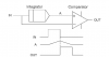
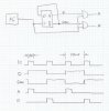
This is what Ive got.

Im working on a project that requires an input of two complementary square waves that have adjustable widths. Im having a hard time working around this or finding a way to produce this type of signal.

I am currently trying to see if I can sync two Function Gen or waveform gen's together to achieve this. But I would like to be able to do it with one signal generator.

I have access to a quite extensive parts warehouse so as long as its nothing too crazy for components I should be able to get my hand on them.

Any ideas of how to go about this?

Thanks in advance for any help/advice.

-Ethan
 
Well its for a circuit that will drive a bi polar pulsar. These two signals will be fed into the circuit that is going to generate the "bi-polar" pulse and then be fed through a transducer. essentially.

Any ideas?

Ethan
 
Well yes it is just an inverted signal but i need to be able to adjust the widths to what ever i choose. Yes they are TTL signals

-Ethan
 
So you have a fixed frequency and need varying duty cycle, you could try using a 555timer to generate the signal and a 7404 to create an inverted output.

How do you want to control the duty cycle?

~Tyler
 
There are many ways to skin a cat.
The other would be to use a LM3524 pulse width modulator.

You have got the oscillator, the variable duty cycle plus complementary outputs in a single package.

EDIT; the LM3524 would not work, the outputs are not complementary but alternating
 
Last edited:
Good point Tyler.

I guess I dint specify. What i actually need is not an inverted signal. Its more like a delayed complement. I'm sorry I should have read over what i had typed earlier. What I was looking for is a signal that will go high then when that goes low the second signal will go high for the same amount of time then the both will be low for the period of the entire cycle.

This is for a circuit that will ultimately use an FPGA to create the signals needed, but the FPGA that we have is surface mount and we don't really have a way of testing the circuit without actually making the PCB. We want to breadboard the circuit first. So I think what im going to do is just build the logic circuit with counters and individual components for testing purposes.

I haven't played with the LM3524 but it sounds appealing I'm going to take a look at it now and see if its something that I could utilize.

Thanks for the suggestions guys.

Ethan

EDIT: I just saw you edit Schmitt Trigger. Ill take a look at it but i think you may be right.
 
Last edited:
I edited before you had sent your very last message, in which you clarified your requirements.

In this instance, I believe the LM3524 may indeed work.
 
I think you may be right. Ive downloaded the data sheet and skimmed it. I will speak with my colleague tomorrow morning and see if it was he thinks we were looking for.

Thanks again for the advice!

Much appreciated!

-Ethan
 
Conceptually, the attached circuit does the job.
 

Attachments

  • Plsdup.png
    Plsdup.png
    1.4 KB · Views: 242
If you have a function generator that has independent control of frequency and pulse width, connect it the Clock input of a positive-edge triggered D Flip Flop. Wire the Qbar output of the DFlop to its own D input. Q and Qbar are complementary.

Now if you want to shorten the two complementary outputs to be the duration as the pulse width of the function generator, wire two AND or NAND gates so that the Q and Qbar outputs are gated by the function generator signal. Now adjusting the pulse width on the function generator gives you control of how long the two outputs last.
 

Attachments

  • 2PhaseLogic.jpg
    2PhaseLogic.jpg
    236.7 KB · Views: 215
Good stuff guys I think both of these ideas will work and be quite easy to construct as well.

Ive been in a meeting all morning and have not been able to put any time into this project yet. After lunch time I will take a closer look and most likely use something similar to the design with the D F/F. I need to get some more solid specs on what kind of signal I need to generate for this pulsar circuit from my colleague.

Im glad I found this forum. Seems to be wealth of knowledge and many knowledgeable people here that are willing to help.

Thanks again guys! Ill let you know what the outcome is!

-Ethan
 
Status
Not open for further replies.

Latest threads

New Articles From Microcontroller Tips

Back
Top