Continue to Site

Welcome to our site!

Electro Tech is an online community (with over 170,000 members) who enjoy talking about and building electronic circuits, projects and gadgets. To participate you need to register. Registration is free. Click here to register now.

  • Welcome to our site! Electro Tech is an online community (with over 170,000 members) who enjoy talking about and building electronic circuits, projects and gadgets. To participate you need to register. Registration is free. Click here to register now.

Competition: High Voltage Power Supply

Status
Not open for further replies.
Interesting thread, just read through all the replies.
My experience with LOPT is that they do overheat very quickly at higher currents.

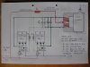
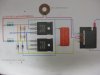
I have built a few ZVS drivers with IRFP250 mosfets (in 2-2 parrallel) , which can switch at 36 Volts 11 Amps to a LOPT with no problems.
Drive current through 5 + 5 turns wound over the ferrite.
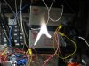
Arcs up to 10 cm can easily be made in open air, most likely a lot bigger in a vacuum.
Pushing 400 Watts out of a LOPT will heat them up in about 1 to 2 minutes.

For portability this set up is not ideal. I use SLA's to supply the current.

Happy to post some pics if someone is interested.

Hey Rodalco, great to hear from you!

The batteries are not required to abide by the size or weight constraints, as they're still reasonably lightweight and won't be mounted on the board. For that reason, a ZVS setup would be allowed.

Pics would be appreciated, I'm sure. Also, if you happen to have any videos, those would also be helpful :D If you want to submit a circuit, we can take it as an entry. Up to you :)

Best wishes,
Matt
 
Zvs

Hi Matt, i will take a few pics and will post these over the next couple of days.
Some of my experimental ZVS footage is attached for whoever is interested.

24 Volts ZVS video

https://youtu.be/0CxpkLe8Ncw

This is from a 24V ZVS driver. The LOPT can handle the 4 Amp at 24 Volts quite well. About 100 Watts output. the driver here is a single pair of IRFP250's.

24 Volts ZVS with double pair of IRFP250's

https://youtu.be/L9xotAWC6cw

I make a new video of the 36 Volts ZVS as I only made a CD burn video of it. ( Look at 6:20 for the actual set up )

https://youtu.be/xNbhCLdGpE8
 
Last edited:
Those are some nice videos guys!

The host has told me he's decided the current isn't critical, and a setup like the one you linked to, KISS, is probably overkill. The main priority is to produce a strong electro-magnetic field in the surrounding area, so a few milliamps should do the trick.

Sorry this project has changed so much over time. I think all the necessary information has been given though. The rest is up to the competitors.

Regards,
Matt
 
Zvs

I created this arc at 36 Volts and a current of 15 Amps.
Electrodes 8 cm apart.
The 1 mil 5+5 primary winding started smoking in about 1 minute.
Schematic attached

Above arcs can be drawn with a single pair of IRFP250 or 260 mosfets.
In double bridge it will allow me to switch up to 60 Amps.

Costs:

4 x IRFP mosfets US$ 8.00
16 x 47nF 1kV Capacitors US$ 10
R's and zeners US 2.00

heatsink free
inductor free
LOPT free
 

Attachments

  • IMG_8618.JPG
    IMG_8618.JPG
    348.7 KB · Views: 2,709
  • IMG_8615.JPG
    IMG_8615.JPG
    459.8 KB · Views: 754
I created this arc at 36 Volts and a current of 15 Amps.
Electrodes 8 cm apart.
The 1 mil 5+5 primary winding started smoking in about 1 minute.
Schematic attached

Above arcs can be drawn with a single pair of IRFP250 or 260 mosfets.
In double bridge it will allow me to switch up to 60 Amps.

Costs:

4 x IRFP mosfets US$ 8.00
16 x 47nF 1kV Capacitors US$ 10
R's and zeners US 2.00

heatsink free
inductor free
LOPT free

Wow, that was very thorough! I guess the final question is, would you like this to count as an entry? You've provided everything required, plus some. :)

Regards,
Matt

EDIT: The one thing that would have to be adjusted is the primary winding that started smoking. The final device should be able to run for 24 hours at a time without overheating or damaging itself.

Hi Matt, I will enter this as an entry. I actually blew up the mosfets and flyback at a duration test. 36 Volts is too high. This circuit will run reliable at 12 or 18 Volts without smoke, and produces a 2 to 4 cm arc at those voltage levels. Video is up on my YouTube channel.
 
Hello,


How about part number for the output transformer?
 
Hello,


How about part number for the output transformer?

Output transformer :
Any type of flyback from an old CRT TV. The bigger the TV the better flybacks, bigger arcs.
29 or 32". but even a flyback from a smaller TV will still give good arcs.

Bit of trial and error with the primary winding 5+5 or 6+6 works well. at 12 Volts a very reliable circuit is made.
 
Hello everyone!

Sorry I haven't been on much, I've been battling the flu and it's taken a lot out of me.

Anyway, I am happy to inform you that RODALCO is the winner of the competition! Thank you to all who showed interest!

Congratulations RODALCO. You should be receiving your prize shortly, if you haven't already.

Thank you for participating!
Best wishes,
Matt
 
Hi Matt,
I have received my prize. Many thanks for that. Will buy some electronic components with it.
Have a great day
Raymond [rodalco]
 
Glad it worked out. Keep us up date with the Reliabliy part though.

Important for me so I can learn too :)

Regards,
tvtech
 
Last edited:
To keep everyone updated, Have been busy with work lately and not enough time for soldering and experimenting with electronics.

Just rebuild my ZVS driver circuit again, damage on the previous blow out at 36 Volts, was 2 out of the 4 mosfets gone and one 12 Volts Zener.
I will do a duration check over a 24 hour period. starting with 12 Volts and see what happens.

I made a single bridge ZVS with IRFP260's. running current is 4 Amps at 12 Volts. nice purple-blue arc of about 1.5 cm long. Had it running for 5 minutes. Flyback TX cold, mosfets cold. Do the duration test tomorrow, want to tidy up some wiring, and will document it for a video. Will keep you all posted.
This test will be followed up with a 18 or 24 Volts run.

During testing I use a 12V60W car head lamp as current limiter in series, just in case something shorts out. When all is ok, the lamp is bridged out and 10 Amp HRC fuse inserted.
 
Last edited:
tvtech

Just completed the 24 hour testrun with no failures.
the ZVS was run at 12 Volts 4 Amps
video attached.

https://youtu.be/2ycpaT3v31o

Highest temperature measured was about 60°C (140°F) with no cooling on the Flyback TX.

The mosfet drivers remained lukewarm. 25°C (77°F)

Higher voltages ( 18 or 24 V ) may be used dependent upon the flyback TX. Oil cooling is a possibility.

Flyback TX was ex 29" TV.

Total cost of the project was as described before. post #125.

Cooling fan free ( ex old computer psu )
 
Last edited:
Hi RODALCO

All still working??

Just checking :) Remember it is supposed to be able to work 24/7. 365 days a Year.

Regards.
tvtech
 
Last edited:
Sorry to revive this Thread..

Is all still working? I need to learn too ;)

Just checking.

tvtech
 
Last edited:
Sorry to revive this thread yet again ;)

All still working ?

Regards,
tvtech
 
For DS8, and any other members who are interested in the schematic and some photo details.
For the tank Capacitors it is better to use a lot of Capacitors in parrallel, better with current sharing and heat dissipation. ( I used here 1 x 470 nF and 8 x 47 nF in Parrallel ) The 470 nF gets hot when run at 24 Volts for a longer time.
Keep the leads short between this Cap and the LOPT 5 + 5 or 6 + 6 coils.
The coils are wound in the same direction with a centre tap. e.g. 10 turns with centre tap makes 5 + 5.
Wire size I used here was 1 mil². running current about 5 Amps at 24 Volts.
The red LED is an indication, so I know the coil is oscillating. just 2 turns a LED and 1 k.Ohm R in series.

I use this driver now to power a simple Tesla Coil which works very well.
( I will make up an other thread with more details if members are interested. )

During testing, especially first test run, put a 12 V 50 or 100 Watt car head light in series. saves blowing up the mosfets in case of a wiring error.
A 10 or 16 Amp HRC fuse is also good to fit in the positive line.
 

Attachments

  • IMG_0006.JPG
    IMG_0006.JPG
    385.4 KB · Views: 670
  • IMG_0007.JPG
    IMG_0007.JPG
    447.3 KB · Views: 692
  • IMG_0008.JPG
    IMG_0008.JPG
    404.6 KB · Views: 754
  • IMG_0009.JPG
    IMG_0009.JPG
    401 KB · Views: 648
  • IMG_9994.JPG
    IMG_9994.JPG
    397 KB · Views: 3,959
Last edited by a moderator:
i would otherwise take part in this competiton, but due to hardware AND safety issues, i pass this one out :D....not that i'm wimp or anything, i just know my limitations ;).
 
Status
Not open for further replies.

Latest threads

New Articles From Microcontroller Tips

Back
Top