Continue to Site

Welcome to our site!

Electro Tech is an online community (with over 170,000 members) who enjoy talking about and building electronic circuits, projects and gadgets. To participate you need to register. Registration is free. Click here to register now.

  • Welcome to our site! Electro Tech is an online community (with over 170,000 members) who enjoy talking about and building electronic circuits, projects and gadgets. To participate you need to register. Registration is free. Click here to register now.

Compaitable part for this diagram, Mosfet , ss contactor etc etc?

Status
Not open for further replies.

Romadon

New Member
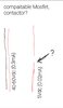
Hey all I need a part number that will fit the diagram below, the power will be "Normally OFF" most of the time, if that makes a difference, I need a contactor/mosfet/transistor that accepts 40-60Vdc as input and can switxh the 5vdc 0.02mA load cheers.
 

Attachments

  • Screenshot_20210517-133909_Chrome.jpg
    Screenshot_20210517-133909_Chrome.jpg
    102.6 KB · Views: 208
Do the 60 V signal and the 5 V signal share a common ground? yes / no

If yes, then:

Two resistors
One zener diode
One n-channel MOSFET

Does this sound like something you can handle?

ak
 
Do the 60 V signal and the 5 V signal share a common ground? yes / no

If yes, then:

Two resistors
One zener diode
One n-channel MOSFET

Does this sound like something you can handle?

ak

AnalogKid I presume so, its on an ebike and the whole thing is powered by the same battery, the load is for a restriction/derestriction trigger on the econtroller, ofcoarse I could just use a switch, the problem is I already have a 3pole switch 1/0/2 BUT the econtroller has only 1 on/off input so pole 1 and 2 on my switch will have to share it, I will put a rectifying diode on pole 2 just before pole 1 and 2 meet at the econtroller for on/off, I will take a spur from line 2 before the diode, like this when pole 1 is selected on the switch the ebike turns ON but the spur on pole 2 wont be Live and the ebike will be restricted, when pole 2 is selected on the switch both poles will be live of coarse no problem, and so will the spur on pole 2, which leads to the contacter im asking about, this contactor closes a circuit on the econtroller that derestricts it.

Anyway about what you asked the circuit for restriction is a single live wire, I presume it shares the same ground with everything else.
I have 0 knowledge about electronics, could you draw me a very rudimentery diagram using my simple drawing as I dont understand schematics, thank you so much for your time. And everyone elses.
 
could you draw me a very rudimentery diagram
Yes, but you first. Too many words, not enough pictures. We like pictures.

Sketch the generator, switch, controller, and whatever else as simple blocks with names, and show the wiring the way it is now. Every wire, every connection. Then modify that drawing with what you want to change, post that, and we'll sort it out. We get that you're new at this and all of that. That is why drawings are so important - they bypass most of the language issues.

ak

AnalogKid I have attached 2 rudimental pictures as requested
 

Attachments

  • Screenshot_20210517-175803_Gallery.jpg
    Screenshot_20210517-175803_Gallery.jpg
    905 KB · Views: 187
  • Screenshot_20210517-175759_Gallery.jpg
    Screenshot_20210517-175759_Gallery.jpg
    1 MB · Views: 195
Muuuuuuuch better. Your probably are using the term "three=pole switch" incorrectly. How many connection points (tabs, pins, screws whatever) are on the switch? If the total is three, then what you have is a single-pole, double-throw (SPDT) center-off switch.

To be clear, the 60 V source is present even when the bike is "restricted"?

Your drawings make me wonder about the 60 V source. If it is a battery connection, then much more than "0.3 mA" is available. A relay or opto-coupler might be a more simple solution.

ak
 
Last edited:
AnalogKid I probably am using the term for the switch wrong, I presumed 3 position setting 1/0FF/2 meant 3 poles, I have attached a photo.

The 40-60Vdc source will be present in both circumstances.

The controller only has 1 signal input for OFF and ON and I dont want to add a dedicated switch for low/high power mode, hence this problem, I will use a rectifying diode on L1.
 

Attachments

  • Screenshot_20210517-180647_Gallery.jpg
    Screenshot_20210517-180647_Gallery.jpg
    698.6 KB · Views: 184
Last edited:
Your drawings make me wonder about the 60 V source. If it is a battery connection, then much more than "0.3 mA" is available. A relay or opto-coupler might be a more simple solution.
 
Your drawings make me wonder about the 60 V source. If it is a battery connection, then much more than "0.3 mA" is available. A relay or opto-coupler might be a more simple solution.

AnalogKid Let me keep this uncomplicated, L1 and L2 are within the specs ive given.

The source is from inside the switch housing, which is also a voltometer and a thumb throttle and communicates and receives power from the controller, via other wires I purposefully left off the diagram because they arent neccesary, none of which are high amperage like the battery.
 
Last edited:
If the 60 V line can be loaded with a 5 mA current path to GND, then we are down to just two components - one resistor and one opto-coupler.

ak
 
AnalogKid I dont know if it can, i.e. the 5mA MIGHT be out of spec for the ON/OFF signal input on the controller I DONT KNOW.

Does a device not exist that can switch 5Vdc (0.02mA) using a 40-60Vdc (0.3mA) as its trigger?

Im about to give up and join L1 and L2 together so they do the same thing, (turn the controller ON/OFF) and add a seperate manual switch for circuit D, but its an extra switch its, messy and it means im defeated, and it means L2 on the original switch is obsolete and that ANNOYS me.
 
Yeah, that would bug me, too. Let me whip up a sketch.

ak
AnalogKid Thanks bro, I tried just adding 5v to the de/restricted signal input but it doesnt do anything the bike stays unrestricted, otherwise I could have just used a buck dc dc stepdown to feed the 5v signal from L1, it seems circuit D has to be physically dis/connected for anything to happen, could it be that the 5v signal input needs to be correct amperage, I fed the signal input 5v at 2a and it done nothing. When I disconnect circuit D and put a meter in the circuit I get the 5v 0.02mA reading. Or could it be that they way the controller reads if circuit D is Dis/connected is from measuring draw on its supply side? Any how I dont want to confuse things, I think you understand my prediciment now, in essence I need a "reverse current relay" like the ones that people with generators and batteries use, when the battery reaches a higher voltage than the generator they relay disconnects the generator circuit, if they done minature versions of this I could put the rectifying diode on L2 so when switch 2 was selected the "reverse current relay" would disconnect the generator (in this case circuit D) because the input would be higher than circuit D and when switch 1 was connected leg 2 would not be powered and the reverse current relay would keep the generator (circuit D) connected and derestrict the bike, but these reverse current relays only come in high load formats.
 
Last edited:
First pass.

NOTE - THIS IS DANGEROUS. A ground problem or inequality between the 60 V stuff and the D inputs could fry the controller in a blink. Just sayin ...

ak
!E-Bike-Enable-1-c.gif
 
AnalogKid Thanks alot for your time, I can manage that diagram.
1. Is the question mark in the controller representing neutral?
2. The Mosfet is slightly confusing me does each pin have 1 wire attached to it and circuit D now has a connection to ground?
 
Those are things I don't know. For this circuit to work, the 60 V source, the controller ground, and one of the "D" inputs all need to be at the same potential - ground. You show a "-" connection to the controller, but don't call it "Ground", which is why I have a question mark there. If this is the system/power ground, then the question is what is its relationship to both of the D inputs. Hopefully, one of them measures 0.0 ohms to that - input.

ak
 
Status
Not open for further replies.

Latest threads

New Articles From Microcontroller Tips

Back
Top