Hi,
We have a new prototype, non-isolated, 150W Offline LED driver which comprises sequence switched Linear LED drivers comprising our new custom designed integrated circuit driver.
There is also a small 1W high voltage buck converter bias supply on it.
We have two versions of this LED driver which are exactly identical, except for the fact that one has eight separate large COB LEDs, and the other has 100 LEDs on a large (18cm x 24cm) piece of MCPCB. Whether its with COBs or MCPCB, the COBs or MCPCB sit on top of a large aluminium heatsink which is earthed.
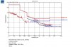
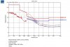
We did conducted EMC scans on both COB and MCPCB versions of this product.
The MCPCB version gives a far worse conducted scan than the COB LED version. (as the attached shows). It’s obvious that this is due to noise capacitively coupling out of the large area MCPCB and into the earthed heatsink. Thus the problem is primarily a common mode noise problem. The “problem frequencys” are from 150kHz to 350kHz. This shows that Common mode conducted problems can manifest at low frequencies like 150kHz.
We don’t have room on this (all SMD) prototype for an off-the-shelf common mode choke, and neither do we have an earth connection wired to the PCB, so we cannot have normal Y capacitors fitted.
However, we are wondering if we can actually have a form of Y capacitance as follows……that is, we could make footprints of Y capacitors and connect them to live and neutral respectively (right near to the live and neutral connector)…..then we find that we don’t have an earth connection to connect the other end of the Y capacitors to…..so what we wish to try, is to literally connect the Y capacitors to vias going through the PCB and onto bare bottom layer PCB copper which sits on the thin rubbery thermal pad which sits on the earthed heatsink….like this we would have an albeit capacitive coupling to the earthed heatsink, and therefore a kind of stray Y capacitance on our PCB.
Do you believe this is a good idea?
..Maybe we could improve it by having a screw going down into the earthed heatsink, and then connecting the earth pad of the Y capacitors to this earthed screw head on the PCB?
..Or what about having the earth wire that connects to the heatsink being put through a manganese torroid (maybe two turns)?
(We don’t have a common mode choke fitted, but we do have inductors in the “+” and “-“ lines of the DC Bus, just downstream of the mains rectifier bridge.)
Alternatively, do you believe fitting ferrite beads in the wires leading to the LEDs on the MCPCB would be a better idea?
We have a new prototype, non-isolated, 150W Offline LED driver which comprises sequence switched Linear LED drivers comprising our new custom designed integrated circuit driver.
There is also a small 1W high voltage buck converter bias supply on it.
We have two versions of this LED driver which are exactly identical, except for the fact that one has eight separate large COB LEDs, and the other has 100 LEDs on a large (18cm x 24cm) piece of MCPCB. Whether its with COBs or MCPCB, the COBs or MCPCB sit on top of a large aluminium heatsink which is earthed.
We did conducted EMC scans on both COB and MCPCB versions of this product.
The MCPCB version gives a far worse conducted scan than the COB LED version. (as the attached shows). It’s obvious that this is due to noise capacitively coupling out of the large area MCPCB and into the earthed heatsink. Thus the problem is primarily a common mode noise problem. The “problem frequencys” are from 150kHz to 350kHz. This shows that Common mode conducted problems can manifest at low frequencies like 150kHz.
We don’t have room on this (all SMD) prototype for an off-the-shelf common mode choke, and neither do we have an earth connection wired to the PCB, so we cannot have normal Y capacitors fitted.
However, we are wondering if we can actually have a form of Y capacitance as follows……that is, we could make footprints of Y capacitors and connect them to live and neutral respectively (right near to the live and neutral connector)…..then we find that we don’t have an earth connection to connect the other end of the Y capacitors to…..so what we wish to try, is to literally connect the Y capacitors to vias going through the PCB and onto bare bottom layer PCB copper which sits on the thin rubbery thermal pad which sits on the earthed heatsink….like this we would have an albeit capacitive coupling to the earthed heatsink, and therefore a kind of stray Y capacitance on our PCB.
Do you believe this is a good idea?
..Maybe we could improve it by having a screw going down into the earthed heatsink, and then connecting the earth pad of the Y capacitors to this earthed screw head on the PCB?
..Or what about having the earth wire that connects to the heatsink being put through a manganese torroid (maybe two turns)?
(We don’t have a common mode choke fitted, but we do have inductors in the “+” and “-“ lines of the DC Bus, just downstream of the mains rectifier bridge.)
Alternatively, do you believe fitting ferrite beads in the wires leading to the LEDs on the MCPCB would be a better idea?
Attachments
Last edited:
