Continue to Site

Welcome to our site!

Electro Tech is an online community (with over 170,000 members) who enjoy talking about and building electronic circuits, projects and gadgets. To participate you need to register. Registration is free. Click here to register now.

  • Welcome to our site! Electro Tech is an online community (with over 170,000 members) who enjoy talking about and building electronic circuits, projects and gadgets. To participate you need to register. Registration is free. Click here to register now.

colpitts oscillator help

Status
Not open for further replies.

darko24

New Member
Hello!

I have to make a Colpitts oscillator working on 1.1 GHz, and another Colpitts oscillator on 1.5-2 GHz.
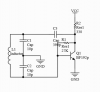
Here is the circuit:
https://imgur.com/a/4irBu
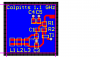
The frequency is about 880 MHz, and i've already tried a lot of different values for L1, C1,C2 but i can't increase the frequency to 1.1 GHz. My professor said that there is no problem with the circuit, so let's try again and again, but i've no more ideas. I've already calculate(Thomson formula) that if C1=C2=1 pF and L1=5 nH, the circuit has to work on 3,1 GHz(??).

So, what do you think? What is wrong, what should i do?

Thank you
 

Attachments

  • upload_2017-10-4_15-42-11.png
    upload_2017-10-4_15-42-11.png
    43.6 KB · Views: 174
Last edited:
Considering the Low Capacitor Values, You also need to Consider Circuit Layout.
Poor Layout May be Adding a Lot of Capacitance.
 
I can not find a BF192p transistor data sheet. Can't find where to get the part. Is this the transistor you are using.
Can you attach a picture of your circuit. (taken with your phone/camera)
 
Good picture, thanks.
Every red trace makes a capacitor to ground. Every inch (cm) of trace makes a inductor.
Look at the red traces going to L1,2,3. They have capacitance to ground.
Populate L3 and remove the traces going to L2,1. This will increase your frequency a little.

upload_2017-10-4_7-59-7.png
 
Sorry, the transistor is BFR92P, C1=C2=1 pF. I can buy just 15 nH inductor, so i had to use 3 parallel to reach the 5 nH. But i can't understand, how design it to 1,1 GHz. I calculated this formula: f=1/(2pi*sqrt(LC)), C= C1XC2, and it is 3 GHz, if i use 1 pF and 5 nH. But i built the circuit, and it's 800 MHz now, and i can't decrease the capaticance to increase the frequency
 
Putting 3 Inductors, Close Together in Parallel will Not give a Correct Inductance.
Close Together will cause them to Act Against Each other, Adding More Inductance than calculated.
 
Last edited:
Your printed circuit board is making capacitors.
A capacitor is two plates of copper with a insulator in between.
You have xpF of capacitance from inductor to ground.
I made a black circle around the two capacitors in the picture below. You do not know about these capacitors.

upload_2017-10-4_8-23-41.png
 
ok, i understand, but calculating 3 GHz, and actually working on 800 MHz??? maybe there is something another thing we didn't realize? for example, this circuit can't reach a value of frequency in reality?
 
From what I see, The Data Sheet for that BFR92P says it should work Up to 2 Ghz.
 
I can buy just 15 nH inductor, so i had to use 3 parallel to reach the 5 nH.
I make inductors by using wire and winging around a pencil. Then remove pencil. Maybe 3 turns.
I have a good meter that will measure 5nH. Spread the wires to decrease the value. Push together to increase the value.
upload_2017-10-4_9-54-35.jpeg
 
Status
Not open for further replies.

Latest threads

New Articles From Microcontroller Tips

Back
Top