HI All,
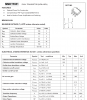
After an extra pair of eyes to see if I've made any cock-ups with this circuit. The requirements are on the screenshot.
This is a cold-boot circuit, it charges some small super-caps to a "turn-on" level of around 2.2v, a boost then enables, turns on an MCU and it shuts down the circuit. It's required because the super-caps have a high-ish impedance of 14 ohm. If current were to run-away the voltage would trigger a "false start" on the boost, the MCU would turn off the circuit and the voltage would sag, tripping the MCU off.
Another circuit then charges the caps efficiently through switch-mode. Thus the point in this circuit is to get the caps to the initial turn-on in a shorter time than a resistor while surviving up to 100v when turned off.
The input supply is a low impedance so sags heavily under load. Under no load 100v is possible, under max load at 500mA it's 20V. Realistically I can expect no more then half that, but they are the extremities.
You can see that the cold-boot (2.2v) should occur at 12 seconds. If the MCU fails to take over (very odd) there is a fail-safe which stops the caps going beyond the rated value.

Query - power input supply is limited to 500mA (incorrectly modeled here) but I've set the current limit of the cold-boot to 180mA via R4, a little below the continuous current rating of the transistors. In real-life the power input is a half-wave rectified signal. What would happen if I set R4 to permit 500mA - will the transistor degrade or will the heat limit the gain and self-regulate it? (due to space requirements I can't use larger transistors). Note that if I draw 500mA from the supply then the absolute max input voltage is 20v. Assuming the caps are at 0.01v, that's 0.5*20 = 10W initial dissipation. Obviously these SOT-363 transistors can't do anything close (0.2W) so I'm expecting that at worse case input extremities they would get hot and burn-out unless self-regulated by reduced gain.
After an extra pair of eyes to see if I've made any cock-ups with this circuit. The requirements are on the screenshot.
This is a cold-boot circuit, it charges some small super-caps to a "turn-on" level of around 2.2v, a boost then enables, turns on an MCU and it shuts down the circuit. It's required because the super-caps have a high-ish impedance of 14 ohm. If current were to run-away the voltage would trigger a "false start" on the boost, the MCU would turn off the circuit and the voltage would sag, tripping the MCU off.
Another circuit then charges the caps efficiently through switch-mode. Thus the point in this circuit is to get the caps to the initial turn-on in a shorter time than a resistor while surviving up to 100v when turned off.
The input supply is a low impedance so sags heavily under load. Under no load 100v is possible, under max load at 500mA it's 20V. Realistically I can expect no more then half that, but they are the extremities.
You can see that the cold-boot (2.2v) should occur at 12 seconds. If the MCU fails to take over (very odd) there is a fail-safe which stops the caps going beyond the rated value.
Query - power input supply is limited to 500mA (incorrectly modeled here) but I've set the current limit of the cold-boot to 180mA via R4, a little below the continuous current rating of the transistors. In real-life the power input is a half-wave rectified signal. What would happen if I set R4 to permit 500mA - will the transistor degrade or will the heat limit the gain and self-regulate it? (due to space requirements I can't use larger transistors). Note that if I draw 500mA from the supply then the absolute max input voltage is 20v. Assuming the caps are at 0.01v, that's 0.5*20 = 10W initial dissipation. Obviously these SOT-363 transistors can't do anything close (0.2W) so I'm expecting that at worse case input extremities they would get hot and burn-out unless self-regulated by reduced gain.