Continue to Site

Welcome to our site!

Electro Tech is an online community (with over 170,000 members) who enjoy talking about and building electronic circuits, projects and gadgets. To participate you need to register. Registration is free. Click here to register now.

  • Welcome to our site! Electro Tech is an online community (with over 170,000 members) who enjoy talking about and building electronic circuits, projects and gadgets. To participate you need to register. Registration is free. Click here to register now.

code does not play fair??

Status
Not open for further replies.

MrDEB

Well-Known Member
been trying to figure out WHY this code keeps outputting regardless of switch setting.
What it is supposed to do is run only the desired IF THEN statements but it runs all four IF THEN statements. If I have the switch on pos4 (Pg4 = pressed then all three leds light up but the code cycles through all four IF THEN statements.
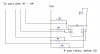
the rotary switch has the common pin grounded and each position pin is held HIGH
Verified that the correct pic pin is going LOW.
her is the switch, kept looking at switch diagram to be sure I didn't miss anything https://www.mouser.com/ds/2/96/220-786387.pdf
this shouldn't be this hard. I used a working example from my Mexican train game that works but the switches are separate momentary on/off but same code format.
IF Pg1=pressed THEN
portA.2=1
portA.3=1
portA.4=1
Ch_10=1 //led on c.5
DELAYMS(1000)
Ch_10=0
DELAYMS(500)
END IF

IF Pg2=pressed THEN
portA.1=1
portA.3=1
portA.4=1
Ch_11=1 //led on d.6
DELAYMS(1000)
Ch_11=0
DELAYMS(500)
END IF

IF Pg3=pressed THEN
portA.1=1
portA.2=1
portA.4=1
Ch_12=1 //led on d.7
DELAYMS(1000)
Ch_12=0
DELAYMS(500)
END IF

IF pg4=pressed THEN
portA.1=1
portA.2=1
portA.3=1
Ch_10=1
Ch_12=1
Ch_11=1
DELAYMS(1000)
Ch_10=0
Ch_12=0
Ch_11=0
DELAYMS(500)
END IF
 
Why am I doing this? I never learn.

First, since the data sheet you linked has switches with a number of different encodings, it's impossible to determine if you bungled the switch choice.

Next, I don't know what's connected to PortA:1-4, but all of your if/then statements are setting some of the set high, with nothing ever setting them low.


Nope. Not gonna do it again. As I read your post to figure out what the heck you're trying to do, and how you know the code is going through each section, I'm totally lost. Until you can write a clear articulated question, with diagrams showing what's actually connected at the moment you run the code to what, no one will probably be able to help you.

Sorry. I have more rewarding things to do.
 
Switches are active low and he probably hasn't turned analogue off.

Mike.
 
I have the switches tied to HIGH via 10K pull-ups
Have setalldigital.bas--maybe need additional code?
Need the portA.0 for ADC
have leds connected to port C.5, D6, D7 using to determine state of switch selection.
}

DEVICE = 18F4321

CLOCK = 8

INCLUDE "IntOSC8.bas"


'INCLUDE "InternalOscillator.bas"

INCLUDE "RandGen.bas"

INCLUDE "Utils.bas"

INCLUDE "ADC.bas"

INCLUDE "SetDigitalIO.bas"


DIM pressed AS BYTE

DIM uS AS WORD

DIM mS AS WORD

// Led port assignments

DIM Ch_1 AS portD.1

DIM Ch_2 AS portD.0

DIM Ch_3 AS portC.3

DIM Ch_4 AS portC.2

DIM Ch_5 AS portC.1

DIM Ch_6 AS portC.0

DIM Ch_7 AS portD.2

DIM Ch_8 AS portD.3

DIM Ch_9 AS portC.4

DIM Ch_10 AS portC.5 // for testing of pwm

DIM Ch_11 AS portD.6

DIM Ch_12 AS portD.7

DIM Ch_13 AS portB.0

DIM Ch_14 AS portB.1

DIM Ch_15 AS portB.2

DIM Ch_16 AS portB.3

DIM Ch_17 AS portB.4

DIM Ch_18 AS portB.5

DIM Ch_19 AS portB.6

DIM Ch_20 AS portB.7


// Rotary switch program select

DIM Pg1 AS portA.1

DIM Pg2 AS portA.2

DIM Pg3 AS portA.3

DIM Pg4 AS portA.4

DIM speed AS BYTE

DIM index AS BYTE


//ADC for SPEED adj

FUNCTION Get_ADC_Sample() AS WORD // Function to grab the ADC sample


result = ADC.Read(0) // Grab an ADC sample from channel 0

result = result * 2 // Scale the answer up by a factor of 2


END FUNCTION


OUTPUT (Ch_1)

OUTPUT (Ch_2)

OUTPUT (Ch_3)

OUTPUT (Ch_4)

OUTPUT (Ch_5)

OUTPUT (Ch_6)

OUTPUT (Ch_7)

OUTPUT (Ch_8)

OUTPUT (Ch_9)

OUTPUT (Ch_10)

OUTPUT (Ch_11)

OUTPUT (Ch_12)

OUTPUT (Ch_13)

OUTPUT (Ch_14)

OUTPUT (Ch_15)

OUTPUT (Ch_16)

OUTPUT (Ch_17)

OUTPUT (Ch_18)

OUTPUT (Ch_19)

OUTPUT (Ch_20)


Ch_1 = 0

Ch_2 = 0

Ch_3 = 0

Ch_4 = 0

Ch_5 = 0

Ch_6 = 0

Ch_7 = 0

Ch_8 = 0

Ch_9 = 0

Ch_10 =0

Ch_11 =0

Ch_12 = 0

Ch_13 =0

Ch_14 = 0

Ch_15 = 0

Ch_16 = 0

Ch_17= 0

Ch_18= 0

Ch_19= 0

Ch_20= 0

// PROGRAM SELECT SWITCH

' Pg1 = 1

'Pg2 = 1

'Pg3 = 1

'Pg4= 1

INPUT (portA.0)

INPUT (Pg1)

INPUT (Pg2)

INPUT (Pg3)

INPUT (Pg4)

speed =(10 + Get_ADC_Sample) //led onfor 10ms plus adc sample x 2

pressed = 0

WHILE True


IF Pg1=pressed THEN

portA.2=1

portA.3=1

portA.4=1

Ch_10=1 //led on c.5

DELAYMS(1000)

Ch_10=0

DELAYMS(500)

END IF


IF Pg2=pressed THEN

portA.1=1

portA.3=1

portA.4=1

Ch_11=1 //led on d.6

DELAYMS(1000)

Ch_11=0

DELAYMS(500)

END IF


IF Pg3=pressed THEN

portA.1=1

portA.2=1

portA.4=1

Ch_12=1 //led on d.7

DELAYMS(1000)

Ch_12=0

DELAYMS(500)

END IF


IF Pg4=pressed THEN

portA.1=1

portA.2=1

portA.3=1

Ch_10=1

Ch_12=1

Ch_11=1

DELAYMS(1000)

Ch_10=0

Ch_12=0

Ch_11=0

DELAYMS(500)

END IF


WEND
 

Attachments

  • switch sch.jpg
    switch sch.jpg
    146.5 KB · Views: 200
MrDEB, you write interesting code. Completely non-functional but someone could spend hours studying how your mind works.

First, although you have included Utils.bas (which includes the command SetAllDigital) and SetDigitalIO.bas (which also has a command to make all inputs digital), nowhere do I see the command to actually set the inputs to digital. But that is the least of your problems.

You are reading 4 bits of port A to determine the status of the switch (which we still can't understand as you haven't said which part you used) which you have dimensions as Pg1 - Pg4. The 4 bits are inputs.

Looking at the first if/then command, you test if Pg1/PortA.1 = pressed / 0. If it is, then you set the other port A bits high? What is it you think you're doing here? Those bits are the state of the switch pins. What are you trying to accomplish?!?!???

Me thinks you are somewhat confused. How much are you charging this guy for your efforts?

tmp_26483-20170522_0854271496679095.png
 
I tried using just
IF Pg1=pressed THEN
Ch_10=1 //led on c.5
DELAYMS(1000)
Ch_10=0
DELAYMS(500)
END IF
but that didn't work either. Then just out of curiosity I tried using %11111101 t indicate portA.1 as LOW
reason for setting the other port pins HIGH was to make sure they are indeed HIGH
My plan is to have 4 separate programs then each switch position jumps to a sub route.Using leds to indicate that the switch is taking the port pin LOW.
I am assuming that by using INPUT portA.1 is enough? for the command to set the port to INPUT. Correct me if I am wrong.
Note I still need to use the PORTA.0 for ADC input.
Not sure if I tried using trisA=%11111111
the IF THEN statements are same as I used for my Mexican Train and it worked but not in this application??
I got something wrong somewhere. Just trying to discover where. I was rechecking the rotary switch and I verified that the port pin inputs are going LOW.
 
pg1 to pg4 are the switch outputs connected to port pins A1, A2, A3, A4
I removed the rereading of the port pins as indicated in post #8
it is reading the switch but it keeps falling through and executing all 4 IF THEN statements.
It should stop only on the first true if then but it goes through all four regardless of switch setting except the pg4 input
 

...First, although you have included Utils.bas (which includes the command SetAllDigital) and SetDigitalIO.bas (which also has a command to make all inputs digital), nowhere do I see the command to actually set the inputs to digital. But that is the least of your problems....
 
command to set the input to digital??
does the setalldigital.bas do that??
I tried TrisA=%11111111 but no different
it appears to just be executing all the code and not following the IF then statements regardless of being true or not
 
I found the missing command!!
setalldigital
now it looks like it works but will be sure with futher testing
 
DIM pressed AS BYTE Cant work no way
Dim pressed as bit
or Dim pressed as boolean

Code:
 pressed = 0
if pressed true 
//do this 
else 
do nothing 
endif

Code:
pressed = 0
if pressed = 1 
//do this 
else 
// do nothing 
endif

Way you have it theres no test
dim pressed as byte
if you your reading more then one switch you need to do something like the
Code:
if portA = $f  
// no switch pressed 
pressed = false
elseif portA  <> $f 
// switch has been pressed
hell I got to here and said why even used press
you need to read the port

Code:
If portA = $F
// do nothing 
endif 
If portA = $7 
// do what you want here 
endif 
If portA = $3 
// do what you want here 
endif 
If portA = $1 
// do what you want here 
endif
 
using Pressed as byte seems to work.
It worked on my Mexican Train code as well.
working on the ADC and a rand number generator code.
 
Your using pressed as a test to see if a pin has changed it don't need to be a byte just a bit or boolean
you reading 4 pins what if you press 2 of them by mistake But if you ok with code that works when it feels like it thats cool.
 
Status
Not open for further replies.

Latest threads

New Articles From Microcontroller Tips

Back
Top