Hi, after a little help here if possible.
a friend has been helping me with this but is having alot of personal problems at the moment so is unable to help me for a while.
Let me explain a little and i'm sorry if this get's confusing or is all muddled up, i find it hard to explain this sort of thing unless i'm face to face
I have a device which has 2 external switch point wires on it, these control what program it's on (ie; P1, P2 up to P5)
These wires are Orange and Green (i know this isn't relevant it makes it easier for me to explain that's all)
When the orange wire is grounded it resets the device from whatever program it's on back to P1.
When the green wire is grounded it set's the device up 1 program, P1 to P2 ect..
-
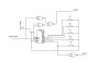
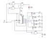
I need a circuit to generate a sequence of pulses when a specific switch is actuated.
The circuit will have 5 switches and will need to ground the orange wire once then ground the green wire relating to what switch was actuated.
ie: if switch 1 is pressed then only the orange wire is pulsed
if switch 2 is pressed then 1 pulse on the orange wire and 1 pulse on the green wire
if switch 5 is pressed then 1 pulse on the orange wire and 4 pulses on the green wire.
I hope i have explained this enough, if not i have some details he sent me through on email to explain tho it's pretty much what i've said i think.
If anyone can help i'd be really greatfull,
Thanks
-Kris
a friend has been helping me with this but is having alot of personal problems at the moment so is unable to help me for a while.
Let me explain a little and i'm sorry if this get's confusing or is all muddled up, i find it hard to explain this sort of thing unless i'm face to face
I have a device which has 2 external switch point wires on it, these control what program it's on (ie; P1, P2 up to P5)
These wires are Orange and Green (i know this isn't relevant it makes it easier for me to explain that's all)
When the orange wire is grounded it resets the device from whatever program it's on back to P1.
When the green wire is grounded it set's the device up 1 program, P1 to P2 ect..
-
I need a circuit to generate a sequence of pulses when a specific switch is actuated.
The circuit will have 5 switches and will need to ground the orange wire once then ground the green wire relating to what switch was actuated.
ie: if switch 1 is pressed then only the orange wire is pulsed
if switch 2 is pressed then 1 pulse on the orange wire and 1 pulse on the green wire
if switch 5 is pressed then 1 pulse on the orange wire and 4 pulses on the green wire.
I hope i have explained this enough, if not i have some details he sent me through on email to explain tho it's pretty much what i've said i think.
If anyone can help i'd be really greatfull,
Thanks
-Kris
Last edited:
")
