Investigate Ohm's Law (E=IR).
Perhaps this circuit will help you understand once you're comfortable with the above concept(s):
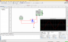
AM1 is an ammeter.
Briefly, the current (I, measured by meter AM1) passing through the resistor (and the diode)
generates the voltage level (VF2) across the resistor as observed in the graph above.
Note the simultaneous
peak positive value difference between VF1 & VF2. That value is the voltage generated (by I) across the diode's resistance when
forward biased, or in this case the positive going sweep of the AC signal. Note also that when the diode is
reverse biased no current flows and thus AM1 and VF2 show, in order, zero current and voltage levels. During this period, VF2 merely reflects the voltage level of the
no-load output of 50Hz sine wave generator.
<EDITED for accuracy and clarity (I hope)>

")