Electro Tech is an online community (with over 170,000 members) who enjoy talking about and building electronic circuits, projects and gadgets. To participate you need to register. Registration is free. Click here to register now.
Welcome to our site! Electro Tech is an online community (with over 170,000 members) who enjoy talking about and building electronic circuits, projects and gadgets. To participate you need to register. Registration is free. Click here to register now.
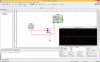
First i admit i am weak on basics.See the image, i am measuring the voltage across the diode.Actually it only passes positive wave,but it also passing negative value.what i misunderstood here.
Can you please explain me the following things
1)Why there must be load resistance,why the diode is not clipping the negative half with out load resistor
2)I cannot differentiate the source ,is that function generator or ac power supply.
3)Let as assume in the above circuit the ac power source is 24 vrms(12v amplitude) 60 hz.if i replace the same with function generator with sin wave of 60hz and amplitude of 12 v
Like you were told on the other two or three websites, your signal generator is a fake simulation that is not real. It has ZERO output impedance so its output signal is not affected when shorted by the diode. A real signal generator output impedance is 50 ohms or more then the diode will cause clipping.
You can also simulate a fake 24V RMS 60Hz signal with ZERO output impedance that will do the same thing. But if you use a realtransformer to supply the 24V RMS then the transformer, the diode or both might blow up or catch on fire.
Some simulators, as AG points out, can allow or improperly respond to circuit behavior that the real world does not allow. For instance, unlimited current through a device which would, again in the real world, release the magic smoke.
In a simple circuit such as that you have given us, adding an output load is just a smart thing to do to assure that your goal (observing the clipping action that a diode has on a sine wave oscillating around ground) is achieved.
Also note the value of the resistor in this case is,essentially, irrelevant but its presence is not, especially at the voltages you cite.
If you measure the current through the diode you will see the problem. The current goes to a very high level with no external resistance added. Also note that the current is rectified. A diode rectifies current not voltage.
AG, what is the difference between a real simulation and a fake simulation?
A real simulation works the same an actual circuit because it has all the spec's for devices. The signal generator in the original simulation was faked because its output impedance was zero and it could supply thousands of Amps of current.
Also the diode was faked because its forward voltage reached 5V when it had thousands of Amps flowing through it.
Simply put, much like a resistor opposes current flow a diode only allows unidirectional current flow, it only allows current to flow in one direction.
okay ,yes it.
But i have heard two things some where ,called voltage curve and current curve.So how do i see the output of clipper circuit is by placing the probes across the diode.so it would be voltage curve and hence it is clipping voltage.Am i wrong?
Perhaps this circuit will help you understand once you're comfortable with the above concept(s):
AM1 is an ammeter.
Briefly, the current (I, measured by meter AM1) passing through the resistor (and the diode) generates the voltage level (VF2) across the resistor as observed in the graph above.
Note the simultaneous peak positive value difference between VF1 & VF2. That value is the voltage generated (by I) across the diode's resistance when forward biased, or in this case the positive going sweep of the AC signal. Note also that when the diode is reverse biased no current flows and thus AM1 and VF2 show, in order, zero current and voltage levels. During this period, VF2 merely reflects the voltage level of the no-load output of 50Hz sine wave generator.
okay ,yes it.
But i have heard two things some where ,called voltage curve and current curve.So how do i see the output of clipper circuit is by placing the probes across the diode.so it would be voltage curve and hence it is clipping voltage.Am i wrong?
The voltage is due to the uni-directional current caused by the diode that flows through the diode and resistor. So the observed clipped voltage is a result of the unidirectional current and the resistance. That's why you saw no clipping when there was no series resistor as in your original post.
You must think about where and how the voltage is being generated and how Ohm's law works. Voltage and current are related entities.
This site uses cookies to help personalise content, tailor your experience and to keep you logged in if you register.
By continuing to use this site, you are consenting to our use of cookies.

")