Continue to Site

Welcome to our site!

Electro Tech is an online community (with over 170,000 members) who enjoy talking about and building electronic circuits, projects and gadgets. To participate you need to register. Registration is free. Click here to register now.

  • Welcome to our site! Electro Tech is an online community (with over 170,000 members) who enjoy talking about and building electronic circuits, projects and gadgets. To participate you need to register. Registration is free. Click here to register now.

Clean DC on an 'antenna'

Status
Not open for further replies.

Othello

Member
I have asked this question in the general area, without any success. This seems the better place for it anyways.

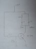
I have to mount a large metal frame on a building, 20' wide and up to 170' in the air.
It is part of the buildings facade.

I will mount more than 12,000 LED's on that frame and supply them with 2.5V.
I will run insulated wires of suitable cross section to these LEDs (those wires are routed inside steel tubing). My ground would be the tubing itself, sort of a large scale coax cable.

The question is the grounding.

Basically I have a huge antenna here, and who knows what I will find on that frame in downtown San Francisco.
Is it better if I connect my frame to the building steel, which makes the "antenna" even larger, or would it be better to separate my frame electrically from the building and use a dedicated and beefy grounding wire just for my installation?

My fear is that spurious AC on my frame will elevate my 2.5 DC and mess up my display.
 
This is an interesting question. I've recently studied the lightning protection practices for radio towers for another project, so the first thing that comes to my mind is whether you need to consider lightning protection or not. The frame is external to the building, but directly against it, so I would think that the building (and perhaps neighboring structures) provides an envelope of protection against direct lightning strike. However, the chances of a lightning surge current coupling to the frame from the building is dependent on how well the building's internal steel is grounded and what kind of lightning protection the building has. On the other hand, San Francisco is not a high lightning probability area anyways. Is this a permanent installation?

The threat of RF voltages and currents depends on a few things. First, I'm wondering what electrical items may react to RF as this tells us what we need to protect. I don't think the function of the LEDs themselves can be affected by RF voltage or current. I do seriously believe that the device that drives the LED feed wires, that is some sort of controller circuit, will definitely need protection from RF at the point where it interconnects to the array. This would follow standard practice in dealing with common mode and differential RF voltages and currents, which is beyond the scope of this reply.

There is also two mechanisms by which you are also likely to cause radio interference. One is the small possibility that your LEDs will rectifiy RF that is induced into the wiring system, and then re-radiate the result. This is a classic intermod generator. The threat mainly exists for very brief times when you are switching an LED on or off, but with so many LEDs I think that, statistically, this may become significant. The other mechanism that we have to consider by which you might cause radio interference is that your wiring will radiate switching transients out into the radio spectrum and pollute the airwaves. I think that you should design to meet FCC part 15 rules for radiation, as a bare minimum.

As for whether you should attach the frame to the building and how, I think the first criteria is safety. Single point grounding is a common concept when wanting to minimize the effects of surge currents. Multiple point bonding would create circulating currents and this seems like a bad idea. I'm a bit out of my depth on this, so perhaps we need to hear from an engineer with more familiarity in the principles of grounding large structures. On the other hand, when you have one conductor running beside another you can have differential surge voltages that cause arcing between them, so for that reason, my gut says to bond your frame to the building in several widely spaced points. While this adds metal volume behind your frame, I don't think that this makes your frame a larger antenna, at least not by much. The effective aperture of the frame alone, vs the frame intimately bonded to the building doesn't seem all that different to me.

Regardless of how the safety bonding is done, you should prepare your driver circuits to repel RF using appropriate filters on all wires that lead up to the LEDs. So, now I'm wondering what the wiring topology will be. Will be creating a large matrix? How will you drive the LEDs?
 
Last edited:
i think filtering is a good idea to avoid emissions. why not put some capacitors in between the wires at various points? should cut down on high frequency current received and transmitted.
 
Thank you for your response.

The installation consists of 600 pieces of 20' long SS 1" x1" square tubing, bolted permanently to the building via 5 vertical columns evenly spaced. The vertical spacing is 6"
Since I will feed the small LED circuit (a reed switch switching a transistor switching the LED) with 2.5 V I have to avoid ohmic losses and reduce cable runs. Each circuit draws 30mA. Therefore the installation will be divided into 5 sub-sections of 20' wide and 30' high. The switching of the LEDs happens randomly thru wind action.
Theses sub sections will then be fed from a power supply located in the geometric center of that subsection in a ventilated NEMA box. The power supply is an adjustable Acopian supply with max. 70 amps.
There are 5 such sections making up the whole installation.
You can visualize each of these subsections as a spine with ribs. The spine is the positive and negative supply bus and the ribs are the symmetrical 10' tubing length holding 20 LEDs each.
If I learn how to upload pictures I can send you a sketch.
 
OK, starting to get the picture. If you are sensing wind, I presume the reed switch and hence the transistor, will be located near each LED, is that right? It is typical to drive LEDs in arrays with constant current control to insure even brightness amongst all the LEDs. Are you not doing this? How do you plan to keep the rain off the LED and other electronics around them?

Depending on exactly where you put the transistor etc. I would definitely consider putting small value ceramic capacitors across the PN junctions that are exposed to long wires. The idea is to bypass all PN junctions in this way so that RF is shorted around them and cannot cause rectification. I hope you have a circuit board or equivalent for each LED to support this.

One other thing that comes to mind is this. I hope you plan to prototype or trial the idea on a smaller or more accessible scale, because this is a unique thing and when things don't work right, you want to be able to modify things to improve it. Access is going to be difficult.
 
Last edited:
No kidding, access is a ***** after we are done.

This is why we prototype everything. I have two small versions out in California, like 3' by 4', and they work fine, for over a year. Even though the circuit boards are unprotected. When they get wet, they might stop, but then they dry out and start up again.

So what you are suggesting are at least ceramic caps on the semiconductors. I had to do this once on a power supply to keep the HF getting into the load, an audio circuit.
I would need 4, since I have a dual color LED, and I guess 2 for the transistor!?
 
I'd like to see the circuit around the LED (the schematic that is).
 
Last edited:
here is my hand drawn beauty:

the 39 Ohm resistor is there to adjust the light balance.
 

Attachments

  • DSC01740.JPG
    DSC01740.JPG
    1.1 MB · Views: 305
Last edited:
Assuming these parts are grouped together, it would be enough for RFI protection to place a small value ceramic capacitor across the transistor from base to emitter, and a second capacitor from the 2.3V input to ground. A reasonable value would be 100 pF at 50V or higher.

Another way to avoid RFI problems is to choose a slower transistor. The one you have chosen has a high bandwidth and high gain. You don't need the bandwidth, so you might consider something with a much lower current gain-bandwidth product, while retaining the desireable features of the BC546 such as low Vcesat.

I am wondering how you control the current flow through the yellow led. Is the 2.3V current limited in some way?
 
Well RadioRon, these parts are placed on a small circuit board of less than 1 square inch, I'd call that grouped together.
I like your idea to avoid RFI problems by picking a slower transistor, I will look into that.

I have no current limiting for the yellow part of the LED, I am relying on the stability of the power supply. Do you consider this a problem?
 
Unfortunately, the slower transistor does not eliminate the need for the two capacitors, but it does decrease chances of other problems happening, and should not cost any more than a fast transistor.

My experience with LEDs is that their luminous intensity is a function primarily of current, but the voltage drop across the LED depends on temperature, and it varies from one LED to the next. Without some means of limiting or controlling the current flow, it will be difficult to maintain a constant intensity when feeding the LED from a constant voltage supply. It will be difficult to insure that current won't exceed the maximum limit of the LED. I am curious what power supply is being used and how each circuit board connects to it. Perhaps the interconnection wiring has served as the current limiting resistance in your trial system.

If your power supply is operating as a constant current source, then it becomes a bit clearer. However in such a case, with many LEDs tied in parallel, some LEDs will take more current than others, resulting in a poorly matched intensities, and there remains a chance of very few LEDs taking most of the current and possibly burning out.
 
Last edited:
I intended to run the circuit boards all wired in parallel in a constant voltage mode and use an Acopian adjustable power supply (Model Y05LX7000).
I mentioned that I wanted to separate the entire installation into 5 subsections, mainly to cope with long cable runs which could lead to voltage drops etc.. So I will need 5 of these supplies, each supplying up to 70 amps.

The LED I was experimenting with has a max current of 20 mA in the yellow and 30 mA in the green, the typical forward voltage is 2.1V, the max voltage is 2.6V.
As I said I measured 30 mA total at 2.3 V supply voltage and I figured that that would keep me in the comfort zone.

Burning out LED's is an absolute no no, you mentioned the difficulty getting up there!!!

I will treat this very conservatively. The power supply has remote sensing capabilities and I think I am going to skip on that just because of the danger of the sensing wires getting ripped off by a window washer, in which case the power supply would go random.

Differences in illumination do not concern me, the LEDs come on randomly and briefly and I am experimenting with their angle (they have a 30 degree viewing angle) so that a person down at the street level will see a bright display. I think the variation in mounting angles will already create differences in perceived illumination, but because of the brief and random operation I do not think this will be a concern.
 
what is the part number of the LED you are working with?

I strongly recommend that you consider some sort of current limiting resistor in series with the LED, either the entire LED or at least the yellow segment. I see your point about not worrying too much about matching the intensities, so focus on avoiding burn-out of the LED.
 
I got these LEDs from Digi Key, #160-1714.
They are manufactured by Liteon where they are called LTL-30EDJ.

And yeah, burning out LED needs to be avoided!
I was trying to think about a way to check on my circuit boards, without actually having to go up there. I couldn't come up with a simple way to do this, so now we will probably propose that someone goers up every 5 years or so and wiggles all the little switches and sees what is broken.
 
I wonder if you could check individual LEDs using an infrared camera of some sort. I would think that a burned-out LED has quite a different heat signature than a good one. They might likely burn out shorted or open and either way they are not generating as much heat as a good one. Of course, you have that problem of waiting for the wind to turn them on. Perhaps a camera with a long exposure time, like many minutes?

I hope you realize that the bigger reliability problem may be that the switches don't last. Anyone who repairs electronics will tell you that it is the electromechanical stuff like connectors, switches and cables that break most often.
 
Here is a bit of information about temperature dependency and the chance of failure:
LEDs Magazine - Driving LED lamps

I'm wondering if we could arrange to use a transistor configuration that naturally limits current by design without adding many parts.

edit: I found some example current limiting circuits on the Instructables site (link below) but in the end, the best example they provided was to use a PTC resistor in series with the LED. This is a good idea as long as you pick the right value of PTC resistor. Such a resistor will increase resistance as it heats up, thereby decreasing current. This works in opposition to the natural tendency of the LED to drop its forward voltage as it heats up, so the PTC can balance the temperature effects of the LED.

http://www.instructables.com/id/Cir...tep6/The-new-stuff-Constant-Current-Source-1/

have a look at this next link, scroll down to the heading "Constant Current".
http://www.specsensors.com/ptc-apps.asp
 
Last edited:
I am a bit surprised by you bringing up the temperature dependency, I had not considered that to be an issue. The LEDs come on very briefly and they are awash in a relatively stable environment, temperaturewise. After all, what could happen to them in San Francisco on the north side of a very windy building site?
Do I overlook something here?

I was on a conference call with the electrical engineer of the building a few days ago, who was definitely not very interested in my concern. The answer was, that if I wanted, they would put additional clean ground connections up for me.
I don't even understand exactly what clean ground in this context means, and more than that I just wanted a check up on my own thinking, but that wasn't happening. Well, they think that is something happens I will be the one changing bulbs, so why should they trouble themselves too much with this.

Today I thought of putting together the little circuit board and mounting it on my antenna tower. Then I can fire up my shortwave transmitter and see what happens.
Destructive testing!?!
 
Sure, put something on your tower and give it a try, it couldn't hurt. On the temperature issue, it is possible I am being overly cautious, but after designing dozens of commercial products over many many years, I've learned to either trust my instincts or gather more data. I would agree with you that the current vs voltage curves for your LED are not terribly steep, but without plotting these at a few different temperatures just to see where we stand, I'm going to stay cautious. There aren't many experienced LED users out there that would go along with powering an LED directly from a constant voltage source without any current limiting whatsover, especially considering that the LED is going to be inaccessible in service. Perhaps you should get another opinion?
 
Status
Not open for further replies.

Latest threads

New Articles From Microcontroller Tips

Back
Top