Electro Tech is an online community (with over 170,000 members) who enjoy talking about and building electronic circuits, projects and gadgets. To participate you need to register. Registration is free. Click here to register now.
Welcome to our site! Electro Tech is an online community (with over 170,000 members) who enjoy talking about and building electronic circuits, projects and gadgets. To participate you need to register. Registration is free. Click here to register now.
It is an amplifier that outputs a digital PWM signal. The amplifier is followed by a lowpass filter to filter out the highfreqency PWM but leave the signal created by varying the duty cycle of the PWM. The period of the PWM is higher than the signal you wish to amplify. These amplifiers have efficiencies of 90% or higher depending on the design.
It is an amplifier that outputs a digital PWM signal. The amplifier is followed by a lowpass filter to filter out the highfreqency PWM but leave the signal created by varying the duty cycle of the PWM. The period of the PWM is higher than the signal you wish to amplify. These amplifiers have efficiencies of 90% or higher depending on the design.
Methinks you mean the frequency of the PWM is higher than the signal frequency being amplified. A higher (longer) period is the inverse of the frequency.
Methinks you mean the frequency of the PWM is higher than the signal frequency being amplified. A higher (longer) period is the inverse of the frequency.
You can get a sine wave out of a class D. Try that with a class C! Class C amps really are used in RF amplifiers in systems using FM or CW modulation. You need class A/B for AM transmissions. Class D works well in the audio range for audio power amps etc.
A class-C RF circuit makes a sine-wave because it has a tuned circuit and works at only one frequency.
I guess we have all heard cheap car audio systems where the sub-woofer is tuned and makes "one-note bass" maybe with a class-C amplifier.
While I do see the point you are making, class c amplifiers are used to amplify FM signals, clearly not only one frequency.
Furthermore, class c amps can and are used in high level AM systems, but they are used before the mixer/modulation step. In other words, it is more efficient to generate high power AM by amplifying the RF frequencies with a class c amplifier, then amplify the audio signal with a linear amplifier (in the right proportions of course), then mix filter etc.
Please don't get me wrong, I'm only pointing out things that I found interesting while learning about different amps. I have a lot of respect for the wisdom and knowledge expressed in this forum by the likes of audioguru, nigel goodwin, kchriste etc. etc. the list goes on. I'm very much in the learning phase, as are many on these forums. I've been a hobbyist for about 15 yrs. but have never taken on electronics as a career, and as such, that is what my knowledge reflects. Happy learning everyone!!
It's effectively 'one' frequency, with a little spread either side - the wider the spread required the lower the gain of the stages. Class C stages require tuned outputs in order to function.
Furthermore, class c amps can and are used in high level AM systems, but they are used before the mixer/modulation step. In other words, it is more efficient to generate high power AM by amplifying the RF frequencies with a class c amplifier, then amplify the audio signal with a linear amplifier (in the right proportions of course), then mix filter etc.
You appear to be talking about high level AM modulation?. You simply generate a high power carrier wave, and directly AM modulate the final stage. The 'transmitter' itself is really just a CW transmitter.
I think he's talking about some large DSB AM transmitters which use a class C output stage; the power supply to this is fed from a large class D audio amplifier which modulates the output.
It's effectively 'one' frequency, with a little spread either side - the wider the spread required the lower the gain of the stages. Class C stages require tuned outputs in order to function.
You appear to be talking about high level AM modulation?. You simply generate a high power carrier wave, and directly AM modulate the final stage. The 'transmitter' itself is really just a CW transmitter.
I was not disagreeing with the fact that a tuned output stage is needed. However to say that a class c amplifier only works at one frequency is clearly incorrect. All tuned amplifiers have center frequency and bandwidth, and the bandwidth on a class c amp is not zero. That is all I am saying.
Yes, I clearly stated, as you quoted, that I was refering to high level AM modulation. But I was not refering to CW. DSB AM is also generated in this fashion.
I was not disagreeing with the fact that a tuned output stage is needed. However to say that a class c amplifier only works at one frequency is clearly incorrect. All tuned amplifiers have center frequency and bandwidth, and the bandwidth on a class c amp is not zero. That is all I am saying.
You mentioned FM.
A 100Mhz FM station has a frequency swing from 99.925MHz to 100.075MHz at max volume. I call that one frequency because the 2nd harmonic at 200MHz and the 3rd harmonic at 300MHz are filtered out by the tuned circuit.
You mentioned FM.
A 100Mhz FM station has a frequency swing from 99.925MHz to 100.075MHz at max volume. I call that one frequency because the 2nd harmonic at 200MHz and the 3rd harmonic at 300MHz are filtered out by the tuned circuit.
My appologies for the misunderstanding. I understood you to mean one frequency when you really meant one channel or station etc. I would not call 100 KHz one frequency. Any class of TUNED amplifier will only operate on a certain bandwidth and a class c amp requires the tuning components (at least to generate a sinewave). However if it is only pulses that you need then the class c amp. can be used at any freq. right?
On a different note, aren't the harmonics of the carrier the easiest to filter out? What about the harmonics of the baseband signal?
Your statement seems somewhat contradictory. Modulation is a multiplicative process and thus is not ever linear. When you mix two frequencies (not to be confused with adding or summing as in audio mixers) such that two new frequencies are created, you have removed all linearity.
Your statement seems somewhat contradictory. Modulation is a multiplicative process and thus is not ever linear. When you mix two frequencies (not to be confused with adding or summing as in audio mixers) such that two new frequencies are created, you have removed all linearity.
An AM modulator is very linear and varies the amplitude of the carrier at the rate of the modulating frequencies. An AM demodulator is just a rectifier and the demodulation is also fairly linear.
An FM modulator is very linear and varies the frequency of the carrier at the rate of the modulating frequencies. An FM demodulator is just a linear f-to-v converter.
A non-linear distorted signal is different. It contains added harmonics. It doesn't have the sum and difference frequencies of a modulated signal.
Linear: having or being a response or output that is directly proportional to the input.
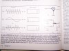
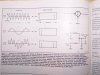
I don't know how else to say it other than you are wrong. To simplify, you supply two frequencies to the input of a modulator, and get two completely different frequencies on the output. That is not linear. Mixing is the function of multiplying the inputs which is not a linear function. The rectifier you refer to does not have an output that is directly proportional to the input. maybe the attached pictures will help you understand.
You showed an AM modulated carrier. The peak voltages of one polarity of it (the modulated carrier that is rectified) are a perfect copy of the modulation. You can even see it.
The multiplication and non-linearity occurs on the carrier and its sidebands, not to the baseband.
The baseband signal will be mixed and, therefore harmonics of the baseband signal will be present in the output. I would not be so adamant if I did not have the information right here in front of me. I feel my resources are reputable and accurate. Mathematicaly, the equation that describes FM AND AM signals clearly show that the relationship between the carrier and the modulating signal is not linear. Look it up.
At any rate, I hope that any beginners that are interested in learning about communications techniques, will study up for themselves so as not to be given false information, perhaps even from myself. I'm sorry that we can not agree, I still value the knowledge and experience you present on this forum and hope that you continue to do so, as I still have much to learn.
Thank you for the stimulating (conversation??). I enjoy hashing out different concepts and I'm sure this will cause me to reread and restudy everything I've learned about amatuer radio thus far. Perhaps some radio guys will chime in here and clarify some things for me, as I do not want to go spreading false information.
The book seems very badly written?, to suggest that the two original frequencies disappear is nonesense!. The output of an RF mixer is the sum, the difference, and the two original signals. IF it's a double-balanced mixer then the originals will only have very low amplitude, and (theoretically) could be non-existant. However, the crude diode mixer ISN'T balanced at all.
As an example of AM, if you have a 1MHz carrier and modulate it with a 1KHz sinewave you will get three output signals.
1,000,000Hz - carrier
1,001,000Hz - sum
999,000Hz - difference
There will be no 1KHz output as it won't pass through the RF stages.
This site uses cookies to help personalise content, tailor your experience and to keep you logged in if you register.
By continuing to use this site, you are consenting to our use of cookies.

")