Continue to Site

Welcome to our site!

Electro Tech is an online community (with over 170,000 members) who enjoy talking about and building electronic circuits, projects and gadgets. To participate you need to register. Registration is free. Click here to register now.

  • Welcome to our site! Electro Tech is an online community (with over 170,000 members) who enjoy talking about and building electronic circuits, projects and gadgets. To participate you need to register. Registration is free. Click here to register now.

Clap switch headache

Status
Not open for further replies.

Skyknight

New Member
Hello all! :D
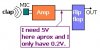
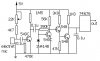
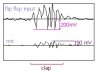
I'm writing my first message in this forum. I have a question for whoever wants to answer it: I've built a clap switch from a schematic I've downloaded from the Internet. Of course, it doesn't work at all. "Scopeing" here and there I've found the problem. Mainly that circuit works as follows: There's a microphone that receives the clap. The signal gets filtered and amplified through four NPN's and finally it's used as a clock signal into a flip-flop which toggles with each clap. The problem is that, after the amplifier section, the signal is not strong enough to excite the clock input as a logic high level. A mean, the signal should be a 5V pulse to make the flip flop change its output. I could find, when clapping, I don't get more than 0.2V in the clock input. I think a way for solving this problem is trying to reach 0.7V. With that voltage I would be able to make a simple common emitter amplifier work and then I would have those 5 needed volts into the clock input of the flip-flop.

So, all I ask for are some ideas to solve the problem. How would you convert a 0.2V pulse signal into a 0.7V, or even better, into a 5V pulse?

Thank you everyone!
 
:? I can't show the original schematic. I'll try to draw a simplified one.

Anyway, my question is almost independent of the circuit: How to convert a 0.2 pulse signal into a 0.7 or more pulse signal :?:
 
Here it is the simplified drawing :p
 

Attachments

  • problem.jpg
    problem.jpg
    13.3 KB · Views: 761
use a trigger schmitt. use 2 trigger schmitt inverters in series. i think that should work. you might use a 4093 NAND gate with schmitt chip. they are highly availabe and cheap.
or use a transistor.....
 
use an NPN transistor. between the amplifier and the flip-flop.
Connect the base of the transistor to the output of the amplifier, the emitter of the transistor to the input of the flip-flop and the collector of the transistor to a 50 ohm resistor. the other end of this 50 ohm resistor goes to Vcc.

If the transistor starts to heat up alot, then increase the value of the resistor.
 
where you say you have 0.2V, do you get 0.2V when oyu clap, or all the time and the voltage increases when you clap. really, a link to the schematic, or the schematic itself will be great. if not on the post, e-mail me. i have built a clap switch and it works fine, but quite low range. now it turned into a touch switch.
 
OK thank you all. I'v tried the NPN solution, but with 220 ohm resistor, the problem is the signals dies when entering that NPN. Another thing is I have 0V when no sound is around and 200 mV when clapping. I'll have a look at the schmidt solution. Than you again. If any new ideas let me now please!
 
whta transistor did you try....? try a darlinghton with a highter gain like BC517(30.000)-i think this is too much....maybe a BC549 of 550 will do the job. and connect the output of the amp to the transistor with a small resistor 10-20R. really i am waithing for you to email me the schematic.
 
Somehow it seams odd that your signal is so weak after 4 stages of amplification. Kinda sounds like one (or more) stage(s) are not working. Might be worth looking into.
 
maybe you have some problems with the amp. what type of mic are you using....? dinamc or electret?
you might have more then 200mV, but your meter might not shouw you all because it is like pulses....(the output)
you might have a burned transistor or something like a disconnected resistor. really, i think that the problem is from the amp, not that you need to increase 0.2 to 5V
 
Thank you again :(
Really I'm getting bored of this circuit. I've been working on it too long. I could borow a super digital osciloscope for today only and I've been testing and changing all I could. I've got the circuit on a PCB. I don't have the schematic in digital format so that's why i didn't showed to you. If I have some time tonight I'll draw it for you. I can tell the four transistors are OK because I've changed them ¿Can a resistor be damaged? If it is possible, please let me now.

OK Here it is the schematic. Is not a Picasso but...
 

Attachments

  • schematic.jpg
    schematic.jpg
    22.1 KB · Views: 795
Thanks for posting the schematic. Unfortunately, everything after the first amp stage seems odd. I'll bet you have a better output at the 'C' of the first transistor than you do at the flip-flop input. Here is a circuit that will work.

**broken link removed**

**broken link removed**

For what it's worth, everyone here has been worn down by a project that just wont do what it's advertised to do. Don't give up.
 
Mmmmm... I'm really surprised with such a fantastic help your're giving to me but :oops: my English is poor and I find it difficult to understand your words:

"Unfortunately, everything after the first amp stage seems odd. I'll bet you have a better output at the 'C' of the first transistor than you do at the flip-flop input."

Odd? Does it mean "unusefull"? What is a 'C' of a transistor? The output (in this case, the collector)?

I know the circuit you propose. I didn't make it because, once ago, I made a simulation with Orcad and it seemed it wouldn't work (lol) But, please, tell me, how do you know it'll work? Like with English, I'm not the "Master of Electronics" :D so I can't really imagine why you know it'll work. One detail I would like to comment is that the output of the circuit will arrive into a PIC microcontroler which will afterwards control the relay. So I don't need anything afterwards the flip-flop.

Another question, how do you know, just having a look at the schematic, that transistors 2, 3 and 4 are unuseful?

Thank you very much to all of you :D
 
The circuit seems of to me. I think you are messing up somewhere.
How did you check the voltage at outout of amplifier? I am sure you must have done it with multimeter. In normal conditions, the transistor must be in saturation, keeping its collector (C) voltage at Vce(saturation)= 0.2V. When you clap, the transistor goes into cut-off (for a very short duration) pulling the collector to 5V and immediately back to 0.2V. Thus you see only 0.2V at the collector using multimeter. If you want to see the 5V pulse, use a Digital Storage Oscilloscope.
 
or you can use a led with a 100uF cap in paralel and a series resitor and see if the led pulses when you have output.
 
I was using a digital osciloscope. I could borow it only for yesterday. But I can keep working with it in worse conditions out of my home. I should take this scope back to the university now. But before I'll tell you what I get with with this aparatus in some points of the circuit. As I'm not any "Electronics Lord of wisdom" maybe I'm not using this scope conveniently. Could you help me?

First of all. This is the scope I'm using:

**broken link removed**

I have a digital multimeter too if needed for anything.

My procedure working with the scope was as follows:

I locate in the screen CH2 for the signal just in the microphone and CH1 for different points through the circuit. Both channels are configured as "AC coupling" (also could be DC coupling or GND coupling) Is this a good choice, or should I put it in DC coupling mode? A virtual screenshot of the scope, being CH1 pointing in the input of the flip flop, when clapping, could be like this:
 

Attachments

  • scope10.jpg
    scope10.jpg
    14.6 KB · Views: 672
Looking at the waveforms, I can conclude that there is a problem in your amplifier section. Have you tried adjusting the sensitivity pot? Even if the value of pot is kept too low, it may cause problem.
 
Lot's of questions.

First off, when help is offered there is no way of knowing your language , knowledge, or experience. You are doing the right thing by asking for clarification.

By "odd", I meant that the circuit was not what I expected. I expected a more common amplification process like each output feeding the next input or a push-pull arrangement. When I saw your schematic and looked at what was happening to the output of the first transistor, I thought that there MIGHT be a problem.

By "C" of the transistor, I meant collector.

I must admit that there is no way to really "know" if a circuit will work. Even with a simulation program there can be buggs. However, when building a simple switch with such a complex design (an amp can be a single chip or a single high-gain transistor), there is a high probability of failure. Knowing how a circuit will react is a combination of experience, familuarity with the parts being used, and the application of a simple design. That is to say that if you have a simple design that is built with common parts, you can use your experience to work out the problems. . . knowing it will work in the end.

As to the second circuit - count the parts. Look at their arrangement. Immagine how the second IC would work with a clap - rather than just any loud sound. It's not so much that I "know" it will work; it is that I have high confidence that I could get it to work.

Having said all that, I believe you will get your circuit working. I think your gain is being blocked by a transistor that is not working. Perhaps you could use that oscilliscope at each stage of amplification (one at a time) to discover a point where there is no gain.

Good Luck!
 
Status
Not open for further replies.

Latest threads

New Articles From Microcontroller Tips

Back
Top