Electro Tech is an online community (with over 170,000 members) who enjoy talking about and building electronic circuits, projects and gadgets. To participate you need to register. Registration is free. Click here to register now.
Welcome to our site! Electro Tech is an online community (with over 170,000 members) who enjoy talking about and building electronic circuits, projects and gadgets. To participate you need to register. Registration is free. Click here to register now.
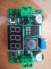
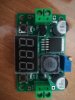
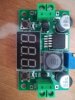
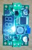
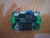
Some background information would be a great help. Is it part of some piece of equipment or did you just find it by the side of the road ? It would also help if you made more effort to focus the camera so the part number could be read on the IC. From the fact that it has an inductor and an IC that could be a switching regulator I think it will be a step up or step down switching regulator module with a display of the output voltage or current. (Or both.) The fact that the capacitor near the input terminals is a higher voltage rating then the one near the output terminal points to it being a step down regulator.
Thanks Les. Actually yes, almost right Almost found by the side of the road as it was mailed to me by mistake (wrong ebay order shipped... So i'm trying to see whether it is useful for something rather than throw it away.)
Correct - I agree with you. Meanwhile I've googled a bit and I think it might be a sort of Step-down Converter Module LED Voltmeter Power - as per link: https://www.ebay.com/itm/LM2596-Buc...623?_trksid=p2349526.m4383.l4275.c10#viTabs_0
Attached some photos - sry could not get the writings clear
What I need to discover the max input voltage and how it work (instead of thrashing it).
Thanks again in advance.
rene'
As the input decoupling capacitor is rated at 50 volts then the maximum input voltage must be less than 50. (I would not go above 40 volts.) I suggest that you look at the data sheet for the regulator IC to see if that has a lower voltage rating.
Just look at the datasheet for the chip, these sort of products basically follow the examples from the datasheets, and the maximum input voltage for the chip will be specified there. As Les has already said, the input capacitor is 50V, and the maximum input to the chip on the datasheet is 45V.
As the pictures provided are so poor then rene' will have to read the part number himself and find the data sheet if it is not a LM2596 (The item on the board in the Ebay link)
It's an LM2596, it's a VERY standard Chinese board, I have some at home. You can even find the schematic on google, although it takes a little bit of sorting through until you find the correct one.
I have one of those. Adjustable 1.5-37V DC/DC Buck Converter with LED Volt Meter
Item #: 30149 PS https://www.mpja.com/Adjustable-15-37V-DC_DC-Buck-Converter-with-LED-Volt-Meter/productinfo/30149+PS
Non Isolated, adjustable DC/DC Buck(Step Down) Converter, switching Regulator with built-in 3digit LED Voltmeter. Pressing Onboard switch cycles through display of: Input, Output & press & hold for Display Off. Regulator
Input: 4.5-40VDC
Input voltage must be 1.5V higher than the output voltage
Output: 1.5-37VDC
Rated Current: 2A
Regulation: 0.5% Meter
Resolution: +-0.1V
Range: 4-40V 4VMin Input Volts to Board for Meter Operation Requires heatsink for output exceeding 10Watts L: 2-5/8" W: 1-3/8" H: 1/2” WT: .06
This site uses cookies to help personalise content, tailor your experience and to keep you logged in if you register.
By continuing to use this site, you are consenting to our use of cookies.

") Almost found by the side of the road as it was mailed to me by mistake (wrong ebay order shipped... So i'm trying to see whether it is useful for something rather than throw it away.)
Almost found by the side of the road as it was mailed to me by mistake (wrong ebay order shipped... So i'm trying to see whether it is useful for something rather than throw it away.)