Hi all,
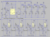
I have a question about my circuit. Which position is better to switch On/Off the injector?
Or to build a driving circuit with NE555 for each injector?
I'm attaching an image to illustrate.
Thanks in advance!
P.S.
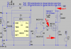
I've decided to use the signal after two transistors gate to MOSFET's gate, to switch injector On and Off. I've tested this on experimental board - it works fine I think.
I have a question about my circuit. Which position is better to switch On/Off the injector?
Or to build a driving circuit with NE555 for each injector?
I'm attaching an image to illustrate.
Thanks in advance!
P.S.
I've decided to use the signal after two transistors gate to MOSFET's gate, to switch injector On and Off. I've tested this on experimental board - it works fine I think.
Attachments
Last edited: