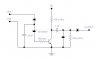
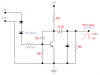
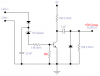
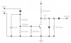
I needed a circuit that would count the number of times a telephone on the line was picked up. I built the circuit below and fed it into a ripple counter with some logic for the output alphanumeric displays. But whenever i lift up the handset nothing happens!
Whenever a handset is picked up, line voltage is dropped to about 9v. The input to the circuit is from a diode bridge attached to the line. The 22n smoothes out any ring voltage (90V RMS). Have i missed something obvious?? is there a better way to do this??
Thanks in advance
Whenever a handset is picked up, line voltage is dropped to about 9v. The input to the circuit is from a diode bridge attached to the line. The 22n smoothes out any ring voltage (90V RMS). Have i missed something obvious?? is there a better way to do this??
Thanks in advance