Continue to Site

Welcome to our site!

Electro Tech is an online community (with over 170,000 members) who enjoy talking about and building electronic circuits, projects and gadgets. To participate you need to register. Registration is free. Click here to register now.

  • Welcome to our site! Electro Tech is an online community (with over 170,000 members) who enjoy talking about and building electronic circuits, projects and gadgets. To participate you need to register. Registration is free. Click here to register now.

circuit simulator

Status
Not open for further replies.

mayankguru

New Member
hi everyone,
i have made first circuit of my life,i was very excited while making it.but really depressed after i saw that it deostn,it works the way it should.
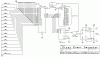
this is the link to the circuit
**broken link removed**

wat this circuit is doing
**broken link removed**
.................................
its simply tells which out of the 16 switches is pressed first. .
i have connected LED's on the putput terminal of the IC2 (Dmux)
and neither of the LED lites up when any of the switch is turned on. . .
what i think is that there might b some connection which is missing in the circuit might b the connection from ic4 to ic3. . or do i have to connect +5 volt to IC1 on its 24th pin

2nd question is that can some one suggest me a circuit simulator for
this circuit. . .
pls help
 
Why don't you attach the schematic "up side up" here, instead of posting it sideways on a different website?

Show how you connected your LEDs.
 
audioguru said:
Why don't you attach the schematic "up side up" here, instead of posting it sideways on a different website?

Show how you connected your LEDs.
i connected the +ve terminal of led to the positive of battery and negative terminal to the output pin(any of the 16) of IC2. .the led lites up only wen connected with the pin 12 of ic2. .
 
I have never seen a 5.0V battery. What is its voltage?

The max allowed output current of a 74LS154 is only 8mA. An LED without a series current-limiting resistor is like a dead short and probably the outputs and the LEDs are blown up.

I cropped your huge schematic and attached it here.
 

Attachments

  • 16_1muxgame_buzzer.gif
    16_1muxgame_buzzer.gif
    14 KB · Views: 2,536
Wait a minute.
You connected the negative of an unknown battery to the output???
You never connect a voltage to an output.

The positive of a 5.0V power supply connects to the positive terminal of the circuit and its negative connects to the circuit's ground.
 
The circuit diagram you have linked to doesn't show the power supply connections (except for the 555 timer). The supply connections are assumed and so to answer your question yes, you need to connect VCC to pin 24 of IC1. You will also need to connect ground to pin 12. The same goes for the other ICs - look up the datasheets to find out what pins the power supply is supposed to connect to!!!

With regard to operation of the circuit, if you're going to connect LEDs to the outputs then you'll need a current limiting resistor. Also, be aware that the 74154 has inverted outputs. In other words, they output high normally. Personally I would suggest you use transistors to buffer the outputs of the IC.

I've had a look at the circuit and I can see how it's supposed to work. Basically the tripple-5 is going to clock the counter continuously and the mux will select each of the button's in turn. It does this very quickly so that as soon as you press a button the output of the mux goes high. This is inverted with a NAND gate (setup as a NOT) which presents a low to one side of the NAND gate connected to the tripple 5. This stops the counter counting, and the Demux on the other side shows which button has been pressed.
Only trouble is, as soon as you release the button the counter will start up again won't it? Which means you only see what button was pressed for as long as you hold the button down?

Someone please correct me if I'm wrong - because that seems a bit pointless!!!

Brian
 
I simulated the circuit in multisim and it ran exactly as I described in my previous post. The only difference between that circuit and my simulated one is that I used a 7493 instead of a 74193 (because the 74193 wouldn't work for some reason)

The circuit works, but it only shows you which button has been pressed for as long as you hold the button. Therefore, it will only show you which event occured first as long as the original event stays valid.

Brian
 
A 555 is a 555, not a triple 5.
A logic inverter is a logic inverter, not a not gate. A logic inverter isn't a gate because it doesn't gate anything. It just inverts.

The stupid circuit doesn't have a latch to remember which button was the first one depressed??? Then it is a very stupid circuit.
 
ThermalRunaway said:
I simulated the circuit in multisim and it ran exactly as I described in my previous post. The only difference between that circuit and my simulated one is that I used a 7493 instead of a 74193 (because the 74193 wouldn't work for some reason)

The circuit works, but it only shows you which button has been pressed for as long as you hold the button. Therefore, it will only show you which event occured first as long as the original event stays valid.

Brian

thanks for ur concern Brian
u said to use 7493 instead of 74193
ok so i will change the counterIC
and for buffer i will be using 4013 (D flip flop)
can u pls mail me the working .sch file which u made at
my email jiitmayank@yahoo.com
its urgent as i hav to submit the project in college ASAP
 
Last edited:
audioguru said:
A 555 is a 555, not a triple 5.
A logic inverter is a logic inverter, not a not gate. A logic inverter isn't a gate because it doesn't gate anything. It just inverts.
I've always called a 555 a "triple-5-timer". I don't see any problems in calling it that personally. I do see your point about the "Not Gate" though. You're right, it's not gating anything (there's a pun in there somewhere), so yes a logic inverter is probably the more correct name to use for it.

I thought *I* was pedantic AudioGuru!!!


mayankguru said:
u said to use 7493 instead of 74193
ok so i will change the counterIC
I am not suggesting you should use a 7493 instead of a 74193 in practice. The only reason I changed to a 7493 was because, for some reason, the 74193 model within multisim didn't want to work. I spent about 40 minutes messing about with it but couldn't get it to count so I substituted it for a 7493 which, when you link both sides of the device together, does the same thing as far as your circuit is concerned.

Please find attached the working circuit. It's a multisim 8 file (zipped up) so you'll need a copy of multisim 8 before you can use it. I substituted push buttons for normal throw switches, and I've named them A-P so when you simulate the circuit you can press a letter on the keyboard from A-P and, after some time (the circuit is MUCH slower in simulation!) the relevant indicator will light up. Press the key again to release the switch and the indicator will go out.

I still don't see what practical use this circuit has - I'd be interested to find out what you intend to use it for?

Brian
 

Attachments

  • ElectroTech1.zip
    176.6 KB · Views: 238
Last edited:
ThermalRunaway said:
The circuit works, but it only shows you which button has been pressed for as long as you hold the button. Therefore, it will only show you which event occured first as long as the original event stays valid.

Brian

I need to make a slight correction in what I've implied there. The circuit WILL show you which event occured first as long as the original event stays valid OR other events occur after it. But as soon as all events have cleared, you will lose the information regarding the first event.

Brian
 
ThermalRunaway said:
I still don't see what practical use this circuit has - I'd be interested to find out what you intend to use it for?

Brian
actually the project is to provide a switch in each flat of a society and the main led panel at the gatekeeper room. so wenever any switch is turned on the gatekeeper will get to know which flat is calling him.
this circuit will decrease the no. of wires used
 
ThermalRunaway said:
It's a multisim file 8 file (zipped up) so you'll need a copy of multisim 8 before you can use it.

Brian
can u attach the setup file of multisim8 also as i m unable to get it from internet. .
 
Unfortunately no, I cannot post the setup file of multisim 8. You will need to purchase a legitimate copy - I'd have thought your college has it installed on their machines??

If you are going to obtain Multisim 8 by illegal means, then that's your bag and I'm sorry but I can't help you with that.

Brian
 
mayankguru said:
can u attach the setup file of multisim8 also as i m unable to get it from internet. .
Not without committing copyright infringement and getting banned from the forum as a result.
 
ThermalRunaway said:
Unfortunately no, I cannot post the setup file of multisim 8.
I'm sorry but I can't help you with that.

Brian

i m sorry its my fault..
neways thanks a lot for ur help. . i appreciate
 
ThermalRunaway said:
Personally I would suggest you use transistors to buffer the outputs of the IC.

hi brian
i hav made the circuit and its working very nicely now whenever i push any switch the corresponding output of the dmux goes low. . .
now there is one very simple problem left
the output remain low only till i keep pressing the button . .i want to use a latch,which can hold the output till it is manually resetted. . .
can u suggest anyway or an IC for this thing . .

thanks in advance


note:using push button is mandatory
 
Hah - I told you that would be a problem didn't I! :D

I'll have to have a think about that one. I've got Welsh classes tonight, so it's going to be tomorrow before I can have a look at it. In the meantime, why don't you try coming up with some suggestions of your own? I'm happy to give advice on anything you can come up with, as are the others on the board I'm sure.

Brian
 
ThermalRunaway said:
why don't you try coming up with some suggestions of your own?

Brian

how about connecting a (s-r latch) IC74ls279 at the output.
datasheet:
https://www.electro-tech-online.com/custompdfs/2007/10/74LS279.pdf

we get low signal at the corresponding output pin of the input applied. . so when the pin gets low the output of this IC (SR latch) will be high and remains high till we manually reset the IC. . .

i think this will work
 
Status
Not open for further replies.

Latest threads

New Articles From Microcontroller Tips

Back
Top