Vini77
New Member
Hi guys, this is my first post here. I expect to be just the beginning. I don't have a background in electronics but completely apaixonado right now. Also, this is my first 'project' and I am here to learn. Sorry in advance by the completely dumb questions. Lets go.
First, I am looking to reproduce this project here: https://circuitdigest.com/microcontroller-projects/arduino-automatic-plant-watering-system
Its a system to automate irrigation. The schema is here:
https://circuitdigest.com/sites/def...c-plant-irrigation-system-circuit-Diagram.png
I have assembled the prototype exactly as the image attached. Before to send the code and plug in the power supply, I have some important questions:
1) As I am very new with circuits and wiring, I would like some help to check if my prototype match the schematics in the original project.
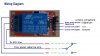
2) In the original schema, the owner did not use a relay module, and in my case, I decided to wire the Signal wire directly into D11. It's ok?
3) In the original schema, the owner used diy soil moisture sensor with just VCC and Ground. In my case, using a ready made sensor there is the Signal output which I have any idea where to wire.
4) Are there something else I am missing? Specially regarding the power supply? I do not want to burn everything again!
I think it is just it for a while!
I would appreciate very much your help and attention. Thanks!
First, I am looking to reproduce this project here: https://circuitdigest.com/microcontroller-projects/arduino-automatic-plant-watering-system
Its a system to automate irrigation. The schema is here:
https://circuitdigest.com/sites/def...c-plant-irrigation-system-circuit-Diagram.png
I have assembled the prototype exactly as the image attached. Before to send the code and plug in the power supply, I have some important questions:
1) As I am very new with circuits and wiring, I would like some help to check if my prototype match the schematics in the original project.
2) In the original schema, the owner did not use a relay module, and in my case, I decided to wire the Signal wire directly into D11. It's ok?
3) In the original schema, the owner used diy soil moisture sensor with just VCC and Ground. In my case, using a ready made sensor there is the Signal output which I have any idea where to wire.
4) Are there something else I am missing? Specially regarding the power supply? I do not want to burn everything again!
I think it is just it for a while!
I would appreciate very much your help and attention. Thanks!
")
 . Old school thinkin' ...