Continue to Site

Welcome to our site!

Electro Tech is an online community (with over 170,000 members) who enjoy talking about and building electronic circuits, projects and gadgets. To participate you need to register. Registration is free. Click here to register now.

  • Welcome to our site! Electro Tech is an online community (with over 170,000 members) who enjoy talking about and building electronic circuits, projects and gadgets. To participate you need to register. Registration is free. Click here to register now.

circuit layout help?

Status
Not open for further replies.

davidg58g

New Member
Hi Guys,

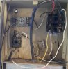
This is my very first post, I am new to the simulator circuit arena, and seeking the assistance in translating this crude drawing, that
I have attached into a working schematic circuit. The drawing shows the layout of a system my boss put in place 20 some odd years
ago to pump-down our parking area when its rains, as it is prone to flooding. The pump-down system has failed and I have been
tasked to analyzes and repair the system since I am the only one at my job with any electronic experience, and since the boss is
85 yrs old and has forgotten how the system work . I am the IT guy and have an A.S.E.E. technology, which I have not used in 25 yrs.
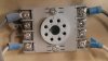
I understand how the system works, I just not for the life of me translate this drawing into schematic form. I have access to
Multisim 12.0, Proteus 8, LTSpice 12 but am unable to find the correct components in neither of the simulators I have access to,
to show the ON-Delay DPDT relay, Need your help! Sorry for being so long-winded. Thanks in advance for any assistance you guys
can offer.
 

Attachments

  • PumpDown.bmp
    1.1 MB · Views: 208
You would be much better off to draw it out in ladder format.
The Schnieder schematic book won't upload as too large, I can send it if you wish to P.M. me an email add.
I will be back later on today.
Max.
 
Ladder is a format for simplifying the display of a circuit.
NEMA standard is the power rails are on each side and the rungs progress downwards.
For IEC the power rail is horizontal across the top and progress down to the bottom horizontal power rail.

upload_2018-5-8_9-37-0.png


It is far easier to trouble shoot than the literal physical format alone.
Max.
 
Cool, thanks. question, can't seem to find a dpdt nc. timed on-delay sw in any of the simulators that I mention above, how is this replicated in say ltspice or multisim? thank
David.
 
Thanks Max for all your help, I know a little more now than I did when I posted this and now I have some tools to expand my knowledge thanks, but I was wondering if someone could show how this circuit is drawn in a circuit simulator such as ltspice or any simulator for that mater, I can't seem to figure out how to make a DPDT ON-Delay timed switch and where are the DPDT motor relays? I have been playing with ltspice all day and i can't find either, like I said I a noob to circuit sims and schematic drawing. I can physically trace out and trouble shoot a circuit, but I would like to see how this is laid out and drawn in a simulator environment thanks
 
Thanks Max for all your help, I know a little more now than I did when I posted this and now I have some tools to expand my knowledge thanks, but I was wondering if someone could show how this circuit is drawn in a circuit simulator such as ltspice or any simulator for that mater, I can't seem to figure out how to make a DPDT ON-Delay timed switch and where are the DPDT motor relays? I have been playing with ltspice all day and i can't find either, like I said I a noob to circuit sims and schematic drawing. I can physically trace out and trouble shoot a circuit, but I would like to see how this is laid out and drawn in a simulator environment thanks

Hi

I can help with that but most of what is needed in LTspice is custom parts. Do you have sample drawing?

eT
 
Looking at your diagram I see you have:

- a float switch
- a 240 VAC pump
- a 120VAC motor contactor to switch the pump 240VAC
- a valve to supply water to prime the pump
- two ON-Delay 120VAC DPDT octal relays

Taking a guess I'd say that the purpose of the circuit is to start and
run the pump when the float switch says there is water to be pumped out,
priming the pump first (or at startup).

The path for the 240VAC is via the contactor to the pump. What drives
the contactor? Oh, pins 6 & 4 of the top delay relay.

But 6 & 4 are opposite states of the two poles of the DPDT relay --
they both won't be connected at the same time so the contactor will
never get power and the pump will never run.

Likely the diagram isn't correct as the circuit would never start the
pump as drawn.

Checking the octal relay pinout I found this:

https://www.alliedelec.com/schneider-electric-magnecraft-750xbxh-24d/70184931

datasheet:

https://www.alliedelec.com/m/d/2b0e135580fd25975728d3f48e6f605c.pdf

Which shows the same pinout as your diagram. So it's likely
the error in the diagram is elsewhere (wrong pin numbers?).

Where did the diagram come from?

The other thing missing is a "neutral" wire/feed. You have
240VAC (two hots) but to get 120VAC for the control circuit
(relays, prime valve, contactor) you need a neutral to get
120VAC from one of the 240VAC hots.

I see this as less a problem of ltspice and more of figuring
out exactly how it's wired...
 
Continued..

Looking at the lower ON-Delay relay, it's powered from one side of the
output of the pump contactor and the "terminal block" for neutral (so
that's the neutral?).

So 120VAC is applied between pins 7/8 and 1/2. This both energizes
the relay (starting the turn on delay) and feeds 120VAC out to
turn on the pump prime. When the time out expires and the
relay "turns on" the 4/5 pins are disconnected and the prime is
turned off.

So this makes sense and implies the (partial) order is:

- motor contactor turns on (somehow)
- lower time relay energized along with pump prime
- on time out prime is turned off (or if contactor opens
since that is where the power for prime is source from).

The upper ON-Delay relay is driven by the float switch also on pins 7/8
and 1/2. When the float switch is "up" pins 7/8 are connected to neutral,
while pins 1/2 are connected to the "blue" hot at the input to the pump
contactor which always has power.

The diagram would make sense if the wires driving the contactor were
connected to pins 6 & 3 (instead of 6 & 4) of the top delay relay.
This would energize the contactor after the top relay delay (so a bouncing
temporary float switch would not start/burp the contactor & pump.)
 
Hey eTech,

Thanks for the suggestion,had a chance to download constructor and play with it, nice... I think this is what I need.
Thanks again
DG
 
Hi Michael8,
Thanks for your thorough examination and explanation of the circuit you are absolutely right sir, the contactor that pulls in the motor / pump should never engaged according to the way the system is laid out. This system was put in place 25 some-odd years ago by the owner of the company who is now 85 years old and he can't remember exactly how it even works but it does work and theoretically it should not I had a conversation with my boss we calling the old man, he does remember the principle operation behind the layout and it is just as you said you were spot-on sir... in that the primer comes on floods the pump and, the pump comes on somehow and then after the designated time expires primer shuts off while pump continues to run until float switch drops out at which time the pump shuts off and in the event the float bounces the top on delay relay prevents the pump from from bouncing, however as you stated the pump should never come on, but it does and has been working for 25 some odd years until just the other day, the relay coil that drives the primer open. Waiting for replacement part and once it's in I will physically walk through the system to see if I can figure out how the pump is being turned on. Thanks for confirming what I thought I was seeing. Now just one thing, like I said earlier I'm can physically draw/trace out a circuit, but when it comes to converting it to a readable schematic, well that's a horse of another color. How would one show this in ladder form. I am currently checking out you-tube may have it figured out in a few days, and in the simulators all of the voltage controled/on-delay switches are spst, how does one modify or make a 8pin on-delay relay. Thanks.

DG.
 
> the contactor that pulls in the motor / pump should never engaged
> according to the way the system is laid out.

Well, if you assume that the wire in the diagram connected to
the top relay pin 4 is really connected to pin 3 it makes sense
(and looks like it would work).

Considering it did work, this is likely just an error in the diagram.

What is the source of the diagram? (asking again)

The ON-Delay relays appear to have a standard pinout for octal relays.
Pins 2 and 7 are the input/energize, pins 1 connects to pin 4 (off)
pin 3 (on), and pin 8 connects to pin 5 (off), pin 6 (on).

> in that the primer comes on floods the pump and, the pump comes on
> somehow and then after the designated time expires primer shuts off
> while pump continues to run until float switch drops out at which time
> the pump shuts off and in the event the float bounces the top on delay
> relay prevents the pump from from bouncing

From the (fixed) diagram, the float switch in the up position activates
the top ON-Delay relay. Assuming the float switch stays up for the
delay period the top relay than activates the motor contactor after
the delay.

The motor contactor starts the pump and also via the bottom relay's
non-energized contacts starts the prime. When the bottom relay
times out it shuts off the prime.

If at any time the motor contactor drops out then the prime ends too
since it's power comes from the motor contactor output.

>the relay coil that drives the primer open. Waiting for replacement part

Oh, the bottom relay failed - so no prime. The pump should still
be starting without prime -- likely not good for it?

> Now just one thing, like I said earlier I'm can physically draw/trace out
> a circuit, but when it comes to converting it to a readable schematic,
> well that's a horse of another color.

I'd just draw the relays as DPDT relays and include their internal
contacts/coils on the schematic. I'd label the pin numbers and keep
careful notice of which contacts were connected when non-energized vs
energized.

Here's a DPDT relay symbol in the lower right corner:

https://upload.wikimedia.org/wikipe...Relay_symbols.svg/464px-Relay_symbols.svg.png

I'd draw it rotated 90 degrees so that the contact wires are horizontal
and change the A B C labels to be relay pin numbers.

> How would one show this in ladder form.

I don't use ladder form. It may be simpler for some people but
that's not me.

> I am currently checking out ou-tube may have it figured out in a few days,
> and in the simulators all of the voltage controled/on-delay switches
> are spst, how does one modify or make a 8pin on-delay relay.

As a software person, if I couldn't just draw the schematic and
"simulate" in my mind, I'd write a short program. Python? Whatever?
 
Industrial control schematics have been shown in ladder format for some decades, the modern replacement for this is PLC ladder which mimics the drawn schematic form, one of the original reasons using it in PLC is it is much easier for maintenance personnel to trace a fault where active devices in any rung are highlighted as conducting, or indicate non-conducting, as the case may be.
Once used to it, it makes trouble shooting very easy, The reason for GM having it developed in the first place.

There are miniature PLC's now called Smart Relays.
PLC Flip-Flop

3a9d937977a19730b54355d9f2b3fe96.png

Max.
 
Last edited:
Hey micheal8,

I am the source of the drawing, I drew it from this (see attached image), and it is as drawn, connected to pin 3. The drawing is
correct and yes if connect to pin 4 and the circuit had a neutral return, I would not see any issues aside from the fact that one of
the on-delay relay coils burned out. thanks

DG.
 

Attachments

  • 20180509_084635.jpg
    20180509_084635.jpg
    1.9 MB · Views: 186
  • 20180505_115532-2.jpg
    20180505_115532-2.jpg
    115 KB · Views: 183
Hey Max,

Is this a representation of my drawing converted to ladder form or is this a generic circuit. I understand the concept of circuit simplification by use of rungs on a ladder, I just don't know how to do it.
 
I will try and draw it up shortly, as already noted there appears to be anomalies in your original!
Max.
 
Hey Guys,

Just to be clear, I have never drawn a schematic of any kind. I do have training in Electronic Engineering Applied Technology, but have never worked in that field, with one exception I wire-wrapping a few prototype boards from a schematic 20 some odd years ago fresh out of college when I work for an Imaging co. I can read schematics to a very small extent but I can't map one out from a hand drawn layout like the one I drew. As for the anomalies in the first attached drawing, the latest photo show the actual enclosure and it's wiring.
thanks guys

DG.
 
Status
Not open for further replies.

Latest threads

New Articles From Microcontroller Tips

Back
Top