Electro Tech is an online community (with over 170,000 members) who enjoy talking about and building electronic circuits, projects and gadgets. To participate you need to register. Registration is free. Click here to register now.
Welcome to our site! Electro Tech is an online community (with over 170,000 members) who enjoy talking about and building electronic circuits, projects and gadgets. To participate you need to register. Registration is free. Click here to register now.
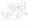
the first 555 is a one shot timer. It outputs one pulse from pin 3 to pin 2 of second 555 (trigger input)
the second 555 is an bi-stable timer. It controls the third timer set up as an astable timer (outputs a train of pulses instead of just one pulse.)
the output of the second controls the third timer.
this circuit can be reconfigured so only one 556 (2-555"s in one package) can be utilized.
Haven't figured out why they put the bi-stable (acts like a toggle switch) in the mix.
look at this site as it explains all of this **broken link removed**
with that posted link - the train can only go in one direction for the circuit to work.
working on an idea that detects model train coming from either direction, using only 2 IC's or using one micro-controller.
also using reed switches is not as reliable as a photo-transistor arrangement.
will get back to you if your interested.
the third 555 is being powered by the second 555 output-I don't think this is a good idea as the output won't drive it or it may cause eratic behavior
at least that's my take on this schematic as well as the train can only go one direction for it to work
Another issue to tackle is that the signal will cancel as soon as the front of the train passes the cancel switch, even if the back of the train is still on the crossing.
planning on using a D flip flop.
have it almost configured by using a divide by two 4013 circuit.
train starts the one shot then the one shot triggers a D flip flop hen when train finishes passing over last sensor the 4013 resets for next train, regardless of direction of travel.
this would be so easy using a PIC but configuring using cmos or TTL is kinda fun.
this circuit detects a train coming from either direction
at least it works in LT spice
cmos could be used instead of TTL and a 556 instead of two - 555's
I'VE SEEN THIS BEFORE!!! When I made my circuit it was not working properly so I switched to a different circuit that uses only one 555 timer as a sinking sourcing circuit.
Don't worry if the circuit doesn't work, it's British, and the Britts do things slightly differently than us Americans.**broken link removed**
This site uses cookies to help personalise content, tailor your experience and to keep you logged in if you register.
By continuing to use this site, you are consenting to our use of cookies.

")