bd13
New Member
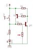
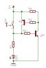
don't take this the wrong way, this is not a simple battery and switch circuit, what i need is a circuit that will activate an LED once a push button switch is...well... pushed. and then when you release the push button the LED continues to stay on, forever...(until you cut the power, then it should turn off...but if it stayed on with no power, then that would be a discovery that would make billions....)
any help would be appreciated.
any help would be appreciated.
")