Continue to Site

Welcome to our site!

Electro Tech is an online community (with over 170,000 members) who enjoy talking about and building electronic circuits, projects and gadgets. To participate you need to register. Registration is free. Click here to register now.

  • Welcome to our site! Electro Tech is an online community (with over 170,000 members) who enjoy talking about and building electronic circuits, projects and gadgets. To participate you need to register. Registration is free. Click here to register now.

Circuit for Strobotac trigger by contact closure

Status
Not open for further replies.

jmb4370

New Member
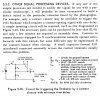
The Strobotac 1531 requires a contact-opening signal with a zero delay in order to fire the strobe as when the camera shutter fires, or when a simple momentary switch closes.

The attached section and circuit is from an out of date book, and I made this circuit but can't get it to work to trigger the Strobotac, despite numerous re-checkings of the schematic, and redos on a breadboard.

Any ideas or suggestions would be appreciated. I don't know enough about inverting circuits to come up with an alternate design, or what components to change.

Michael

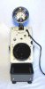
I think it is actually the Strobotac 1531 AB, and I have attached an image of the unit.
 

Attachments

  • StrobotacTrigJCP_Diagram1.jpg
    StrobotacTrigJCP_Diagram1.jpg
    245.8 KB · Views: 251
  • Strobotac1531.jpg
    Strobotac1531.jpg
    18.9 KB · Views: 202
Last edited:
Yes, that is the one, and that is the same manual I have from the same site...

Any advice with the trigger circuit? It can be made to trigger on a switch closure with about a 30 milisecond delay, but to get to zero delay, it has to be on the switch opening.

And yes, it still works, and really well. It must have been refurbished as it is in excellent condition!

Michael
 
I guess my first question would be: "Does it work with just a simple switch closure on the input?" A quote from the manual:
External Triggering: Either a switch closure across
the input jack terminals, a 1-V peak positive pulse, or
a 0.35 Vrms sine wave down to 100 Hz, increasing to
3.5 Vrms at 5 Hz.
So, your circuit above should trigger the unit.
 
The above circuit doesn't seem to work for me, despite trying different capacitor values, and different input voltages. Does the circuit appear to indeed be an inverter circuit where the output goes low when the momentary switch contact is closed? The capacitor value of 0.01 uF is indeed 10 nF, and to be sure, my multimeter verified the value was 10 nF. Is the 100 volt rating of the capacitor an issue in this circuit, and in the schematic, it is drawn with one curved line. I though that was just the old way of drawing a capacitor, or is there some other significance I might be missing? The two 1-Meg resistors are a pretty normal item, so the only other item that can be an issue is the capacitor! Any other suggestions would be appreciated; it should be simple enough!

A simple momentary switch closure will trigger the strobe, but there is about a 30 milisecond delay. To get to a zero delay, this model 1531 must trigger on the switch opening! Newer models work on a switch closing, but this doesn't help me at the moment.

When I put the multimeter on the output, and then close the momentary switch, I don't get a voltage drop on the output.

I have found another circuit to try that uses transistors for a NOT gate (inverter), but it seems that the above circuit should work...


Michael
 
Last edited:
jmb4370 said:
Is the 100 volt rating of the capacitor an issue in this circuit
Definitely. If you look at the schematic for the 1531, you'll see that you can have up to around 100V on J1 (the external input) so you don't want to skimp on the capacitors voltage rating.
When I put the multimeter on the output, and then close the momentary switch, I don't get a voltage drop on the output.
You won't see the pulse with a meter. You'll need a scope to see that.
Another issue could arise if the 1531, power source, and/or your "camera" share the same ground circuit. They need to be isolated for the circuit to work. If they must share a common ground then a transistor type inverter would be the solution.
 
I changed out the ceramic cap I was using with 2 identical cap each 0.022 uF in series to give the 0.01 uF with 100 volt rating, and instead of a regulated power supply, I used a 12 volt SLA battery, so the 1531 and power supply would have separate grounds. The momentary switch has no ground, as it is just a switch closure, isolated from the circuit...still no flash of the 1531.

As an aside, as described in the manual, turning the RPM dial fully CCW, the strobe will flash on contact closure but with a 30 milisecond delay. The flash can be seen in the image taken by the camera, but this will not work for all tests where the exact shutter contact is needed for the strobe to fire.

Any other thoughts here before I move on to a transistor circuit inverter?
 
You could try changing Rb from 1M:eek:hm: to 100K:eek:hm:. This would give a larger pulse when the shutter switch closes.
 
Thanks for the suggestion... but it also made no difference. :(

I also tried changing the resistor pair with different sets: 10K, 1K, 100 ohms; still nothing!

If I short across the capacitor, and then remove the jumper, the strobe fires (on the contact opening). With that, I know the wiring from the breadboard into the strobe input jack is working...

I tried all the different ranges for the external input... for something that should be so simple, it sure isn't!

Michael
 
You could also try a larger capacitor. Maybe try a 0.1uF 100V one. Your 1531 is probably out of spec as far as it's trigger voltage/speed is concerned. I'm no expert on vacuum tubes so I can't help you there unfortunately.
 
I finally went to a 1.0 uF cap (100 times the schematic), but then to get the Strobotac to trigger, I had to adjust the sensitivity down from the recommended.

I then switched to a 2 transitor inverted circuit, and it worked perfectly with a true zero delay on the contact switch!

I will probably also try this using a NOT gate IC, which looks like should work also. (I might need to ask more questions when I get to that trial.)

Thanks for your help and suggestions!

OT:
Have you used any of these software titles, or any other circuit simulation (and PCB) software that might be better, or less costly?

"Circuit Wizard" , "LiveWire", "PCB Wizard 3", "TINA Electronics Software"

It appears that "Circuit Wizard" might be a combination of the "Live Wire" and the "PCB Wizard 3", and all of the titles are offered in Hobbyist, Professional, and Educational versions.

Michael
 
Status
Not open for further replies.

Latest threads

New Articles From Microcontroller Tips

Back
Top