Continue to Site

Welcome to our site!

Electro Tech is an online community (with over 170,000 members) who enjoy talking about and building electronic circuits, projects and gadgets. To participate you need to register. Registration is free. Click here to register now.

  • Welcome to our site! Electro Tech is an online community (with over 170,000 members) who enjoy talking about and building electronic circuits, projects and gadgets. To participate you need to register. Registration is free. Click here to register now.

Circuit building

Status
Not open for further replies.

Maximat

New Member
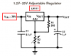
Hi, I'm new in here and my knowledge about electronics is very little. From time to time I have some small circuits to build and I like to do them, but other times I find only diagrams and I don't know how to read them and convert them to the board. I try hard but sometimes I get mixed up and even end up burning some components. The following is a simple diagram which I tried to read, but I would like someone to tell me if I've done this good or not.

**broken link removed**

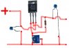
and this is how I thought it has to be connected

**broken link removed**

This has to be fitted into a very small space, so I don't know if I can assemble it onto a strip board.

Kindly advise.
Thanks
 
If you looked on the datasheet for the LM317 then you will see your circuit but it uses a more expensive LM117, not an LM317.
The LM317 needs to have a 120 ohm resistor and a 2.5k trimpot so its output voltage doesn't rise when there is no load.

You connected the trimpot wrong and did not connect the input ground to the output ground.
 

Attachments

  • LM317 again and again.PNG
    LM317 again and again.PNG
    9.8 KB · Views: 181
  • corrected.JPG
    corrected.JPG
    42.5 KB · Views: 276
I need this circuit to use it with a 1.5Volts (max. 3V ) bulb or LED, so that it lights up to a full brightness at low voltage but when more voltage is applied it won't burn out. The maximum voltage to be used is not more then 16 VDC ( mostly it will be 14.8 VDC )

Kindly advise if this is still possible with the components I have at hand.

Thanks
 
hi agu,
Its my teatime, so I'll back off and leave this in your capable hands:)
 
Maximat said:
I need this circuit to use it with a 1.5Volts (max. 3V ) bulb or LED, so that it lights up to a full brightness at low voltage but when more voltage is applied it won't burn out. The maximum voltage to be used is not more then 16 VDC ( mostly it will be 14.8 VDC )

Kindly advise if this is still possible with the components I have at hand.

Thanks

hi,
If the maximum voltage is say 15Vdc
Setup your LM317 to give say, +9V.
If the LED has a forward voltage drop of 1.5V at 20mA ,then you require a resistor in series with the +9V and the LED.

The value of the resistor is calculated as:-

Rseries= (9 - 1.5)/0.02 = 375:eek:hm: , nearest pref value is 390:eek:hm:


If you use a 3V LED operating with say 30mA
Rseries =(9-3)/0.03 = 200:eek:hm: nearest 220:eek:hm:

Does this help?
 
Last edited:
I assembled it as Audio showed me, ( cause I started before you posted yours Eric. It works, so to say with the bulb, but when I try to regulate the pot, it doesn't add light slowly, but sort of in steps, from dimm to bright, even if I just turn it a few millimeters.

I will try next adding the other resistor as you suggested
 
For a 3V light bulb to be dim then it needs about 2V.
Your circuit has an output voltage that will try to go as high as 28V. So 2V is turning the trimmer up only a few millimeters.

Look at the schematic on the datasheet that I attached. Its minimum input voltage is 28V when the resistor is 240 ohms and the pot is 5k.

When the resistor is 120 ohms then a 200 ohm pot will let the max output voltage be 3.33V and the minimum voltage is 1.25v.
 
Ok, this is done and works, but is there any other, more compact way of replacing this whole circuit. I am trying to put all this in a very tight place, and the only space I have is for a bulb and maybe a transistor.

I will use the above for other projects, but for the one I'm in at the moment, its too big.
 
Maximat said:
Ok, this is done and works, but is there any other, more compact way of replacing this whole circuit. I am trying to put all this in a very tight place, and the only space I have is for a bulb and maybe a transistor.

I will use the above for other projects, but for the one I'm in at the moment, its too big.

hi,
If you just use an LED rather than a lamp, you could use a series resistor direct from the Vin, say about 15V.

Again use the formula: Rseries = (Vin - Vled)/ Iled.
eg: Rs = (15-3)/0.03 = 400:eek:hm: say 390:eek:hm: [this is a white LED]

Wattage of Rseries = (15-3) * 0.03 = 0.36W, use a 0.5W

Got the idea?
 
but the resistors reduce the voltage, so if I make a reduction for teh 3V LED, it will only light up at its full brightness when the voltage is at 16 VDC*. I am applying this light to a voltage controller that goes from 0 to 16 VDC*, at 4 volts I have something else that will be activated, so what I want is for teh bulb or LED to be at full brightness before the controller is set to 4 Volts or higher.

* PSU will be either 16 VDC or 14.8 VDC
 
Maximat said:
but the resistors reduce the voltage, so if I make a reduction for teh 3V LED, it will only light up at its full brightness when the voltage is at 16 VDC*. I am applying this light to a voltage controller that goes from 0 to 16 VDC*, at 4 volts I have something else that will be activated, so what I want is for teh bulb or LED to be at full brightness before the controller is set to 4 Volts or higher.

* PSU will be either 16 VDC or 14.8 VDC

hi,
I would like to help, but you must give me an idea about the whole project, what are you trying to do:confused:

Do you have a full sketch?
 
OK this is nothing out of this world, the whole project is about a model Railroad. The loco engines normally have a 16 VDC lamp on them, but since the locos are never run at ful speed, but normally at the lowest speed ( approx 6 volts ) the lamps are very dim, and not realistic. So I wanted to create something to make this more realistic, and the first item that came to my head was teh above, actually someone suggested me to use a TO-92, but then this was rated in milliamps and was not good to light a 1.5V bulb.

Now there are people who run DCC layouts, but I'm still on manual and not looking forward for DCC, even because my layout is small and not worth investing in DCC. Certain engines then have very little and compact space in them, so there's not much possibility in placing large components in them, like one that I'm trying on, it only has a space for approx a transistor or 2 as an extra space inside.

Kindly advice about any idea that might help.
 
Use a series resistor, a zener and an LED. Simplest way to get an LED running at a constant brightness from a fluctuating power supply.
 
Its sound simple enough, does the above formulae work for this combination?

(I'm a super noob in electronics, as said earlier, I only know how to assemble kits :S )

and what's the zener diode for? I know that the diodes are normally used to let curent flow one way only.

is the 1N4007 a zener too? or only the glass ones are zener?
 
Last edited:
Maximat said:
Its sound simple enough, does the above formulae work for this combination?

(I'm a super noob in electronics, as said earlier, I only know how to assemble kits :S )

and what's the zener diode for? I know that the diodes are normally used to let curent flow one way only.

is the 1N4007 a zener too? or only the glass ones are zener?

hi,
The 1N4007 is a 1amp 700v rectifier diode.
How much current does the 2.5V lamp take ? [ or its wattage will do]
 
Maximat said:
Well I don't know exactly but I will check with the meter and post again

hi,
The reason for asking, is so that the value of the resistor can be calculated, also it will decide the rating of the zener. [if you go that route]
 
OK I managed to check the bulbs, but I could only test it on the following voltages

On 1.22 Volts (battery) it gave me 0.09 Amps
On a wall power supply 3.43 Volts it gave me 0.14 Amp

This is what all I could do.
 
Maximat said:
OK I managed to check the bulbs, but I could only test it on the following voltages

On 1.22 Volts (battery) it gave me 0.09 Amps
On a wall power supply 3.43 Volts it gave me 0.14 Amp

This is what all I could do.
hi,
If we then said 100mA at 2.8V for the lamp OK.
I understand that you have a LM317 regulator on the bench?

Connect it as a current limited source to give 100mA.

Its not the ideal way to do this, but as you are limited for space it will work.
The LM317 will get warm/hot,, build it on the bench first to try it.

Calculate the resistor using the formula on the drawing.
 
Last edited:
Status
Not open for further replies.

Latest threads

Back
Top