Electro Tech is an online community (with over 170,000 members) who enjoy talking about and building electronic circuits, projects and gadgets. To participate you need to register. Registration is free. Click here to register now.
Welcome to our site! Electro Tech is an online community (with over 170,000 members) who enjoy talking about and building electronic circuits, projects and gadgets. To participate you need to register. Registration is free. Click here to register now.
A choke filter is just that, a filter. In most cases an ideal choke filter would filter out all AC noise and only let through a DC signal, so you will see them in a lot of powersupply circuits. All components are not ideal though, so it will let through very low frequency AC signals, but filter out the high frequency AC signals, still letting through DC.
You need to learn about inductive reactance then you will more fully understand what I'm talking about.
Purely reactive components do not generate noise. SO, it is not a source of noise. The small series resistance of the conductor is subject to generating thermal & shot noise but these are very small.
Are you refering to a normal mode or a common mode choke? How well they work as a filter depends on the frequency of operation among other things. The choke/inductor typically looks inductive over a range of frequencies (may be narrow or large) until it becomes capacitive looking at some sufficiently high frequency. If you build a single pole filter(for example) with one of these, it will only be effective over the range of frequencies that the inductor/choke looks inductive.
IF the filter is normal mode, it will filter normal mode signals (including noise). By how much it attentuates the noise is a function of the inductor values & number of poles in the filter.
Normal mode filters do not filter common mode signals and vice-versa.
would inductors make noise if you put two near each other? and how do you put dc throught a choke if a choke is two inductors wired onto one core or am i thinking of somthing else, if so what is a choke?
I've tried to find a relatively precise definition of a choke but without much success. A choke is a specific kind of inductor. A choke, like other inductors, is usually described by it's inductance, among other characteristics. A choke is often used to filter or block AC and pass DC where the AC, noise or non-DC component is thrown away -for lack of a better description. Sometimes inductors are used to store power or create a resonant circuit - or when put close together there is coupling and a transfer of power. In these cases we don't "throw" away the AC - so it would seem the inductor characteristics would be such that the AC is returned efficiently. This is the best I can do. I too am interested in a better definition of choke.
The way I use the term "Choke" is when the inductor is a (significant) current-carrying inductor.
Not an inductor in a tuned cct or small-signal stuff but in big power supplies (say and amp or so) where it's presence "chokes" the change in flow of current
would inductors make noise if you put two near each other? and how do you put dc throught a choke if a choke is two inductors wired onto one core or am i thinking of somthing else, if so what is a choke?
would inductors make noise if you put two near each other? and how do you put dc throught a choke if a choke is two inductors wired onto one core or am i thinking of somthing else, if so what is a choke?
True.
A common mode choke has the same configuration. It actually acts as a transformer for differential signals, with the flux from each side cancelling that of the other, which makes the common-mode choke "invisible" (ideally) to differential-mode signals. When you see coax making a turn or two through a toroid, that's also common-mode choke.
Choke is nothing but inductor. It's inductance is causing reactive resistance to AC currents.
XL=w*L
If you place it in series with your load it will attenuate signals with unwanted frequencies to pass your load. It will not block them but only attenuate. Higher is the frequency higher is the attenuation up to frequencies where the parasitic capacintance of choke starts to play a role.
Choke filter can be made a single coil or double coil. Double coil filter can be connected in two ways. One way is when we want to attenuate common mode interfearing signals and other is for differential signals. Double coil filter has its coils connected in both wires live and common or in positive and in negative supply wires.
As 'bloki' says, a choke is nothing but another name for an inductor, as suggested throughout this thread it's more commonly applied to power inductors used in power supplies (particularly the HT smoothing choke in a valve amplifier). However, it's also commonly applied to much smaller inductors, how many of you have heard of 'RF chokes'?, a very commonly used component in the past.
I would suggest that perhaps a choke is an untuned inductor?, whereas an inductor itself would most commonly be tuned?.
Quote:
The small series resistance of the conductor is subject to generating thermal & shot noise but these are very small.
==>I have a schematic below that draw the inductor equivalence circuit below.. it has an equivalence series resistor inside an inductor and also a capacitor, is it right? please tell me how do the shot noise occur in the inductor, i read from a book and it said that the "shot noise is a random fluctuation that accompanies any direct current crossing a potential barrier. The effect occurs because the carriers (holes and electrons in semiconductor) do not cross the barrier simultaneously, but rather with a random distribution in the timing for each carrier, which gives rise to a random component of current superimposed on the steady current. the name shot noise was first coined in connection with tubes, where the analogy was made bertween the electrons striking the plate and lead shot from a gun striking a target." so, please tell me how could the shot noise occurs in the inductor since there are no barrier/pn junction inside the inductor? is it any other definitions about shot noise?
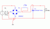
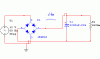
==>i have two schematic below, one is use the choke filter, another one only use the capacitor as a filter, when we use the choke filter/inductor as a filter, the output drop, it must be caused by inductive reactance (XL = 2.pi.f.L), right? please tell me what is the small fluctuation in the output signal of the choke filter? is it the thermal noise n the shot noise? when we use the capacitor as the filter, the noise doesn't occured in the output signal (please look at schematic below), so, is it mean that the inductor also cause the noise to the circuit? if the capacitor is better than the inductor since it doesn't have the output drop, and also don't have any noise in the output signal, why should we use the choke filter for example in switching mode power supply design?
==> what is the meaning of normal mode choke? and the common mode choke?
==>what is the meaning by number of poles in the filter?
Quote:
The small series resistance of the conductor is subject to generating thermal & shot noise but these are very small.
==>I have a schematic below that draw the inductor equivalence circuit below.. it has an equivalence series resistor inside an inductor and also a capacitor, is it right? please tell me how do the shot noise occur in the inductor, i read from a book and it said that the "shot noise is a random fluctuation that accompanies any direct current crossing a potential barrier. The effect occurs because the carriers (holes and electrons in semiconductor) do not cross the barrier simultaneously, but rather with a random distribution in the timing for each carrier, which gives rise to a random component of current superimposed on the steady current. the name shot noise was first coined in connection with tubes, where the analogy was made bertween the electrons striking the plate and lead shot from a gun striking a target." so, please tell me how could the shot noise occurs in the inductor since there are no barrier/pn junction inside the inductor? is it any other definitions about shot noise?
==>i have two schematic below, one is use the choke filter, another one only use the capacitor as a filter, when we use the choke filter/inductor as a filter, the output drop, it must be caused by inductive reactance (XL = 2.pi.f.L), right? please tell me what is the small fluctuation in the output signal of the choke filter? is it the thermal noise n the shot noise? when we use the capacitor as the filter, the noise doesn't occured in the output signal (please look at schematic below), so, is it mean that the inductor also cause the noise to the circuit? if the capacitor is better than the inductor since it doesn't have the output drop, and also don't have any noise in the output signal, why should we use the choke filter for example in switching mode power supply design?
==> what is the meaning of normal mode choke? and the common mode choke?
==>what is the meaning by number of poles in the filter?
SHot noise was the wrong term (sorry!) Resistive conductors carry thermal noise and "Excess" noise similar to shot noise (proportional to the current flowing through them. The excess noise is noise in addition to the thermal which can have a 1/f spectrum. See "flicker" noise for this type of noise.
These sources of noise are indsignificant in your application. I wouldnt worry about them at all. The noise you are talking about is more related to ripple voltage/current than small signal noise sources.
If you think the noise is gone because you used capacitor instead of inductor, try again. In your capacitor, look at the current through it.
In a real capacitor, an equivalent series resistance will convert the ripple current into a ripple voltage.
Number of poles in a filter is a frequency domain concept. If you write the transfer function of your filter in the frequency domain say, Vout(s) / Vin (s) and you find the values that make the denominator = zero, those are poles. The number of these values is equal to the number of poles.
Quote:
The small series resistance of the conductor is subject to generating thermal & shot noise but these are very small.
==>I have a schematic below that draw the inductor equivalence circuit below.. it has an equivalence series resistor inside an inductor and also a capacitor, is it right? please tell me how do the shot noise occur in the inductor, i read from a book and it said that the "shot noise is a random fluctuation that accompanies any direct current crossing a potential barrier. The effect occurs because the carriers (holes and electrons in semiconductor) do not cross the barrier simultaneously, but rather with a random distribution in the timing for each carrier, which gives rise to a random component of current superimposed on the steady current. the name shot noise was first coined in connection with tubes, where the analogy was made bertween the electrons striking the plate and lead shot from a gun striking a target." so, please tell me how could the shot noise occurs in the inductor since there are no barrier/pn junction inside the inductor? is it any other definitions about shot noise?
==>i have two schematic below, one is use the choke filter, another one only use the capacitor as a filter, when we use the choke filter/inductor as a filter, the output drop, it must be caused by inductive reactance (XL = 2.pi.f.L), right? please tell me what is the small fluctuation in the output signal of the choke filter? is it the thermal noise n the shot noise? when we use the capacitor as the filter, the noise doesn't occured in the output signal (please look at schematic below), so, is it mean that the inductor also cause the noise to the circuit? if the capacitor is better than the inductor since it doesn't have the output drop, and also don't have any noise in the output signal, why should we use the choke filter for example in switching mode power supply design?
==> what is the meaning of normal mode choke? and the common mode choke?
==>what is the meaning by number of poles in the filter?
What do you mean why use in switching mode design? You show a crude linear power supply design. In this design, your noise will be related to 120Hz components due to the full wave rectification. It will be reduced by your two pole filter (L & C). Diodes in this circuit produce shot noise & negligible thermal noise. Load resistor produces thermal and excess noise. Purely reactive parts of L & C producce no noise. BUT all of these noise sources are swamped out by 120Hz ripple component by many orders of magnitude.
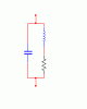
The way your choke is shown, implies a normal mode choke. A common mode choke would filter only signals common to both your supply rail & ground rail & would be shown with a different symbol. I dont think you need concern yourself with it based on the example you are experimenting with.
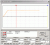
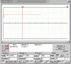
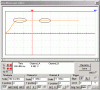
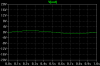
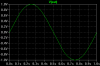
In this copy of your scope shot (below), if you think the aberrations that I have circled are noise - they're not. They are quantization artifacts of your instrument if this is from an oscilloscope, or from your computer or monitor if this is a simulation (which I think it is).
As Optikon pointed out, thermal noise in an inductor is the least of your worries when you are making a power supply. In my 40+ years as an engineer, I have never heard the subject mentioned, in any circuit application.
quote:
What do you mean why use in switching mode design?
i am sorry, in the previous message, i mean in switching mode power supply design (SMPS) ..
can you please give me a simple schematic example of common mode choke filter..?
what is the meaning of quantization artifacts? i simulate the circuit with a software (multisim) i just want to know, because i heard from my lecturer, he said that inductor is the source of noise.. so i try to simulate it in the simulation software to find out which one work better as a filter, and i see the abberation if i use inductor, so i think it's the noise.. i am sorry... hehe..
Regarding quantization artifacts:
Here are two plots of the exact same sine wave, plotted on different scales. Notice the increased visibility of steps in the bottom plot. The voltage source being plotted has no steps. I simulated this on Linear Technology's SwitcherCAD III, but the results will look the same on almost any simulator. The vertical drafting resolution is not very good. The waveshape gets quantized (digitized) by the limits of the plotting software and, to a lesser extent I think, the hardware (the raster on your monitor).
If you were to zoom in on that noisy portion of your simulation (before you save it as a graphic), the noise would go away.
quote:
What do you mean why use in switching mode design?
i am sorry, in the previous message, i mean in switching mode power supply design (SMPS) ..
can you please give me a simple schematic example of common mode choke filter..?
what is the meaning of quantization artifacts? i simulate the circuit with a software (multisim) i just want to know, because i heard from my lecturer, he said that inductor is the source of noise.. so i try to simulate it in the simulation software to find out which one work better as a filter, and i see the abberation if i use inductor, so i think it's the noise.. i am sorry... hehe..
I'd recommend you forget about excess, shot, 1/F noise & all such things for what you are working on. These are not part of what you are seeing in your plots. I think you caused much confusion about your original question of an inductor causing noise. They don't in the strictest sense but your circuit does! or your measurement does! and that's what we are really talking about here. Read this for a first hit google example on common mode chokes.
**broken link removed**
Dont confuse this with the other sources of intrinsic noise talked about earlier. I doubt your instructor believes that inductors can _source_ noise. Where would the energy come from? Your circuit causes noise! Energy source is from your 60Hz generator. Having both and L and C in your circuit is better (noise-wise) than having just a single L or a single C. You have a two pole filter instead of one pole.
This site uses cookies to help personalise content, tailor your experience and to keep you logged in if you register.
By continuing to use this site, you are consenting to our use of cookies.

")