Continue to Site

Welcome to our site!

Electro Tech is an online community (with over 170,000 members) who enjoy talking about and building electronic circuits, projects and gadgets. To participate you need to register. Registration is free. Click here to register now.

  • Welcome to our site! Electro Tech is an online community (with over 170,000 members) who enjoy talking about and building electronic circuits, projects and gadgets. To participate you need to register. Registration is free. Click here to register now.

Chinese DT830B Digital Multimeter repair

Status
Not open for further replies.

indigo

New Member
Could someone help me to repair this DT830B digital multimeter, Please?

Problem is can't measure DCV and it gave me 1 only.

pls see video.


This happened when I tested the 300 DCV with Diode mode in somehow.

I saw the R5 in the circuit board is burnt.


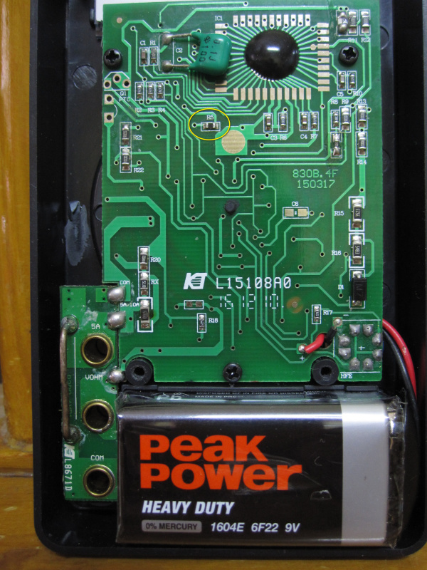
Is it the cause and what is the value?
Or what else should I check?
Please give me advice.

Thanks in advanced.
 
Last edited:
Are you looking at R5 or the same bit I am at the bottom next to RX where it looks a little vapourised ?
Looks like the burnt bit to me... Also if the shunt is gone, that would explain the erroneous readings

I love the solder job on the cap top left... Real quality... R5 looks okay.. I just assumed the shunt was the one he was talking about..
 
Looks like the burnt bit to me... Also if the shunt is gone, that would explain the erroneous readings

I love the solder job on the cap top left... Real quality... R5 looks okay.. I just assumed the shunt was the one he was talking about..
I'm talking about R5 at the middle of the board.
New picture & video added at 1st post.

I measured with analog meter and got nothing.
 
m830b-schematic-diagram.gif

generic 830B schematic R5 = 900K

Link https://www.hobby-hour.com/electronics/m830b-schematic-diagram.gif
 
Looking at the resistors in that sequence, with 90K and 9K above, I believe it's 900 Ohms, not 900K.
Yeah!! That's why I linked the original so you could zoom in... It definitely said 900K.. It weird that those "others" are so far away...

Both those circuits are the same.. So it looks like a typo on the one I found... 900 ohm then..
 
Yeah!! That's why I linked the original so you could zoom in... It definitely said 900K.. It weird that those "others" are so far away...

Both those circuits are the same.. So it looks like a typo on the one I found... 900 ohm then..
Thanks for your confirm.
But what I don't understand is why the other resistors value are not same?
For example ....
In my DMM R2, R3, R4 are 470K
In the diagram they stated different value.

Another 1 odd thing what I found is ...
The R21 value is 900 if I'm not mistaken. but compare with R5 in size.
R21 is bigger, is it normal?

There seems to be lots of different meters using the same model number, with differing component values and reference numbers. So it's a matter of trying to find the exact one that matches your meter.

The larger resistors are simply a higher wattage.
 
All the values will be similar... They are just renamed slightly different..

Look from the diode from D1.. Your circuit is R15 R14 R13.... Branch is R16 ( 5483 )

Circuit I posted From D1.. R24 R25 R26... Branch is R14 and R18 ( two 2743 's) So you need to follow the tracks..

As a start R4 and R5 on the diagram are R22 and R21 on yours... Only you can trace them...
 
I would try 900, as 900K is too high to be easily blown.
I tried with 1K resistor (I don't have 900 right now) and the result is the same.
But the other problem seem to be solved.
That was the diode test mode.
B4 replacing the R5 with 1K, the diode test mode display random digit.
After replacing with 1K, the diode test mode is OK.

What else should I check?
What is the R6 value? 1M !!
I measured with analog meter and got 30x1K ( red probe on top), 7x1K (red probe at bottom)
Is R6 blown?


Look from the diode from D1.. Your circuit is R15 R14 R13.... Branch is R16 ( 5483 )

Circuit I posted From D1.. R24 R25 R26... Branch is R14 and R18 ( two 2743 's) So you need to follow the tracks..

As a start R4 and R5 on the diagram are R22 and R21 on yours... Only you can trace them...
Thanks for the guide. But I don't know how to?
The only thing I can do is measuring resistors.
 
Status
Not open for further replies.

Latest threads

New Articles From Microcontroller Tips

Back
Top