Hello,
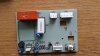
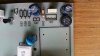
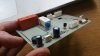
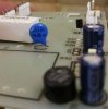
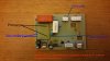
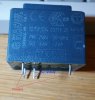
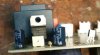
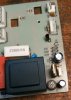
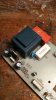
Please can anyone help me identify this PCB transformer, shown in the attached photo. (The large blue transformer)
The Chest FREEZER Whirlpool AFG 605 DGT was bought in France.
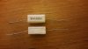
It states on the blue transformer that the secondary output is 66V 2VA............but this seems very strange to me ?????
Very high voltage for a PCB board ?
Is it possibly 6.6v ???
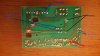
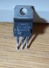
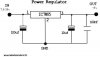
The Borocco L7805 CV Voltage Regulator (which is downstream of the blue transformer) states that the voltage IN is between 7.5 and 35v
so the secondary output on the blue transformer does not make sense !!!
Any help would be much appreciated, especially on where to get a replacement transformer.
(From the markings on the transformer I can see it was made in Italy, but cannot make out the name of the Company)
Thank you
John
Please can anyone help me identify this PCB transformer, shown in the attached photo. (The large blue transformer)
The Chest FREEZER Whirlpool AFG 605 DGT was bought in France.
It states on the blue transformer that the secondary output is 66V 2VA............but this seems very strange to me ?????
Very high voltage for a PCB board ?
Is it possibly 6.6v ???
The Borocco L7805 CV Voltage Regulator (which is downstream of the blue transformer) states that the voltage IN is between 7.5 and 35v
so the secondary output on the blue transformer does not make sense !!!
Any help would be much appreciated, especially on where to get a replacement transformer.
(From the markings on the transformer I can see it was made in Italy, but cannot make out the name of the Company)
Thank you
John
")
 My wife loves Paris!


 You can't make any meaningful measurements with a multimeter, except to check for dead short circuits.