Hi all...
After seeing this idea mentioned a few times on various threads, I gave it go...
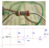
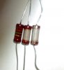
The resistor's shell (R8) was scraped off... As the resistors core absorbs moisture the reistance varies...
It seems to be very sensitive and very fast.... It will detect the moisture from my finger from about half a cm... it takes less than half a second to respond either way...
To test if it was sensing the heat instead of the moisture, I tried a wet piece of paper... and also tried wrapping my finger in plastic.. In both cases, it seems to be sensing only moisture...
Perhaps this will be of some use to some one...
Michael
After seeing this idea mentioned a few times on various threads, I gave it go...
The resistor's shell (R8) was scraped off... As the resistors core absorbs moisture the reistance varies...
It seems to be very sensitive and very fast.... It will detect the moisture from my finger from about half a cm... it takes less than half a second to respond either way...
To test if it was sensing the heat instead of the moisture, I tried a wet piece of paper... and also tried wrapping my finger in plastic.. In both cases, it seems to be sensing only moisture...
Perhaps this will be of some use to some one...
Michael
 ... i really-really appriaciate,if you help for our project design
 hm:. [Edit: That's not taking into account the tolerance of the resistors.]