Continue to Site

Welcome to our site!

Electro Tech is an online community (with over 170,000 members) who enjoy talking about and building electronic circuits, projects and gadgets. To participate you need to register. Registration is free. Click here to register now.

  • Welcome to our site! Electro Tech is an online community (with over 170,000 members) who enjoy talking about and building electronic circuits, projects and gadgets. To participate you need to register. Registration is free. Click here to register now.

Charging battery

Status
Not open for further replies.

drakesou

New Member
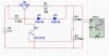
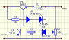
Hi all, I have built a simple charge regulator for my 1.2V NiMH battery. I am using 6V solar panel to charge the battery. Without charge regulator, the charging current is up to 70mA but there is only up to 3mA if connected with charge regulator. Hope someone could help.
 

Attachments

  • charge.png
    charge.png
    199.5 KB · Views: 236
The charge regulator can provide a stable output voltage of 1.44V. When the voltage at W1 (the voltage across emitter and base of Q2 + voltage across D3) reaches 1.3V, Q2 conducts and shut the Q1 down that stops charging.
 
The charge regulator can provide a stable output voltage of 1.44V. When the voltage at W1 (the voltage across emitter and base of Q2 + voltage across D3) reaches 1.3V, Q2 conducts and shut the Q1 down that stops charging.

hi,
The circuit dosn't work in the way you describe, who designed the circuit.??
 
many thx for ur reply !
How can I modify the cirucit to have such ability ?

hi,
This is your original circuit with the absolute minimum number of changes... its not a charge circuit I would recommend.

The RED lines on the plot shows the effect of changing temperatures on the charge current.

Can you buy any sort of voltage reference, eg: TL421.???
If yes we can improve this circuit.
 

Attachments

  • AAesp04.gif
    AAesp04.gif
    31.7 KB · Views: 213
hi,
This is your original circuit with the absolute minimum number of changes... its not a charge circuit I would recommend.

The RED lines on the plot shows the effect of changing temperatures on the charge current.

Can you buy any sort of voltage reference, eg: TL421.???
If yes we can improve this circuit.

Yes, as the temperature goes up, Q2 will conduct earlier to stop the charging current.
I just want to know is there any possible to achieve the ability that I described before with not much modification on the circuit ?
 
Yes, as the temperature goes up, Q2 will conduct earlier to stop the charging current.
I just want to know is there any possible to achieve the ability that I described before with not much modification on the circuit ?

hi,
I have just posted the minimal circuit, just use your original transistors..
The transistors I used were for simulation only..:)
 
What kind of circuit can you suggest if LM317 is used ?

The circuit should be able to provide regulated output voltage and adjust the output current if needed.
 
What is the maximum current you want to charge at? What is the voltage from the solar panel in the sun? What kind of battery?
 
Last edited:
What is the maximum current you want to charge at? What is the voltage from the solar panel in the sun? What kind of battery?

1.2V NiMh battery. maximum charging current is 200mA. The solar panel is 6V@200mA but its maximum voltage in the sun is 6.6V.
 
Hi, I just finished the test of the circuit and it still gave a quite low charging current of up to 5mA. The output voltage is up to 1.49V.

Hi,
You said that you wanted to reduce the charge current close to zero when the battery voltage was ~ 1.44V.
The values you have posted indicate thats what the circuit isdoing.???
 
Can i replace laptop lithium battery with niMH battery?

Sure. If the voltage and current ratings are the same. However, you can NOT charge it in the laptop if the laptop contains the Li charging circuit.

They require 2 very different charging algorithms.
 
Status
Not open for further replies.

Latest threads

New Articles From Microcontroller Tips

Back
Top