Electro Tech is an online community (with over 170,000 members) who enjoy talking about and building electronic circuits, projects and gadgets. To participate you need to register. Registration is free. Click here to register now.
Welcome to our site! Electro Tech is an online community (with over 170,000 members) who enjoy talking about and building electronic circuits, projects and gadgets. To participate you need to register. Registration is free. Click here to register now.
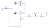
I collected it from internet.. in this circuit with the help of 10KΩ resistor I can change the duty cycle.. I need a solution to change the frequency without changing the capacitor C2.!!!
thanks in advanced...
Try inserting a 500K pot (or, perhaps, even greater value) between pin 1 and the wire connected to pin 1. That should influence the trip points of the circuit, and thus the frequency, leaving the duty cycle adjustment, and range of adjustment, largely unaffected. The pot should influence the trips points due to voltage drop across it resulting from the small amount of input bias current of the IC.
Try inserting a 500K pot (or, perhaps, even greater value) between pin 1 and the wire connected to pin 1. That should influence the trip points of the circuit, and thus the frequency, leaving the duty cycle adjustment, and range of adjustment, largely unaffected. The pot should influence the trips points due to voltage drop across it resulting from the small amount of input bias current of the IC.
I'm using 1MΩ variable. in that case i encountered a problem and that is > I adjust the frequency with the 1MΩ and adjust in 53KHZ or 59KHz or 110 KHz anything. the frequency is not stable. it is always shifting to the near value whether it is less or bigger. if i adjust it in 55KHZ it is continuously moving between 54KHZ to 58kHZ.. all the adjust I made have the same problem.. what should I do now????
I don't think there is much you can do about the less than ideal stability. The circuit is not exactly an example of good frequency stability to begin with, even without the added pot, though certainly more stable without it. The input current into the IC pin 1 is probably voltage dependent (not to mention temperature dependent) and the voltage naturally has to vary at the input for the circuit to operate. What you might try is putting a 200 pF capacitor directly at pin 1 to ground in an attempt to reduce the effect of the variance of the input current probably caused by the voltage dependence of the smaller, internal input capacitance.
An alternative route is get rid of the series pot at pin 1 altogether, put a 10K pot in series with each of the two diodes, and replace the existing 10K pot with a short circuit. The duty cycle adjustment will not be independent of the frequency adjustment, but the ON time of the pulses is adjusted with one of the pots, while the OFF time is adjusted with the other pot. So, at least, the ON time and the OFF time are independently settable, allowing you to adjust the frequency and duty cycle.
An alternative route is get rid of the series pot at pin 1 altogether, put a 10K pot in series with each of the two diodes, and replace the existing 10K pot with a short circuit. The duty cycle adjustment will not be independent of the frequency adjustment, but the ON time of the pulses is adjusted with one of the pots, while the OFF time is adjusted with the other pot. So, at least, the ON time and the OFF time are independently settable, allowing you to adjust the frequency and duty cycle.
can you suggest me what IC (rather than 74HC14) should i use as frequency generator where i can also change the duty cycle. and that should be within the range of 3V (VCC of the IC)???
can you suggest me what IC (rather than 74HC14) should i use as frequency generator where i can also change the duty cycle. and that should be within the range of 3V (VCC of the IC)???
There is only one, but not big one!!!
with the both 10 KΩ I have to fix the duty and frequency.. but the problem is that these two factors( duty cycle and frequency) are changing with the other one. I mean at the time adjusting the duty cycle the frequency is changing a lot and vice versa!!!!!
at a moment I am not able to change the frequency because the 10 K pot went it extreme and the giving frequency is about 35 KHz or something like that in a particular duty cycle.....
You can connect the pots as shown in this attached. The Freq and PW are independently settable. The issue with this configuation is that the duty cycle is adjustable from only 0 to 50% when the Freq is adjusted to the lowest value (0 to 100% when the Freq is adjusted to the highest value). The thing to do then is to add an inverter, as shown, and use the OUT2 to get the 50-100% side of the duty cycle.
You can get independent frequency and mark-space control with a four-gate circuit. Mark-space ratio is adjustable ~ 8% to 92%. If I can attach the schematic successfully it's here:
Edit: I used a CD40106 because of its symmetrical Schmitt threshold values. You could use a 74HC14 instead, but you might have to tinker with R1 and R4 values to allow for threshold asymmetry.
You can get independent frequency and mark-space control with a four-gate circuit. Mark-space ratio is adjustable ~ 8% to 92%. If I can attach the schematic successfully it's here: View attachment 69848
Edit: I used a CD40106 because of its symmetrical Schmitt threshold values. You could use a 74HC14 instead, but you might have to tinker with R1 and R6 values to allow for threshold asymmetry.
That's nice of all of you that you all guys are helping me here..
I'll try your circuit certainly but with 74HC14.. because at this moment i dont have the IC CD40106... but later I'll try to collect it and include it in the circuit......
You can connect the pots as shown in this attached. The Freq and PW are independently settable. The issue with this configuation is that the duty cycle is adjustable from only 0 to 50% when the Freq is adjusted to the lowest value (0 to 100% when the Freq is adjusted to the highest value). The thing to do then is to add an inverter, as shown, and use the OUT2 to get the 50-100% side of the duty cycle.
I have just doing your circuit in my bread board and I'm getting this..
I set the fre 45KHz at 80 % duty. then I try to get 50% duty cycle at the same frequency(45KHz). if Im adjusting the 10KΩ pot for 50 duty cycle automatically the frequency comes to 50Khz...
and the frequency is not getting smaller than 28 or 27 Khz at all the duty cycle I have tried...
I have just doing your circuit in my bread board and I'm getting this..
I set the fre 45KHz at 80 % duty. then I try to get 50% duty cycle at the same frequency(45KHz). if Im adjusting the 10KΩ pot for 50 duty cycle automatically the frequency comes to 50Khz......
Not perfect independence, admittedly, but not bad for a simple circuit. Different pot settings load the inverter differently and the inverter has limited drive capability. Even in the very first circuit you posted, the frequency would be expected to change slightly while varying the duty cycle.
and the frequency is not getting smaller than 28 or 27 Khz at all the duty cycle I have tried...
Naturally, there are limits on the adjustment due to pot values and capacitor value.
BTW: I don't understand how you getting such a high frequency output with a 0.1uF cap and those pot values. It should be a factor of 10 less than that. Are the component values changed?
This site uses cookies to help personalise content, tailor your experience and to keep you logged in if you register.
By continuing to use this site, you are consenting to our use of cookies.


")