Continue to Site

Welcome to our site!

Electro Tech is an online community (with over 170,000 members) who enjoy talking about and building electronic circuits, projects and gadgets. To participate you need to register. Registration is free. Click here to register now.

  • Welcome to our site! Electro Tech is an online community (with over 170,000 members) who enjoy talking about and building electronic circuits, projects and gadgets. To participate you need to register. Registration is free. Click here to register now.

Ceiling Fan Digital Speed Control using MCU

Status
Not open for further replies.

haxan

New Member
Hi,

I am trying to make a digital speed controller for ordinary ceiling fans using a Microcontroller (PIC).

I am trying to divide speeds into 10 portions ( Off, 10%, 20% .... 100% )

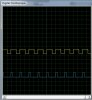
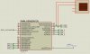
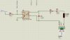
I know very little regarding controlling speeds by varying phase of AC power which a lot of ppl do with triac's. I have attached a circuit diagram of MOC3022 attached with a triac and was wondering if i could use similar concept. Also i know very little of PWM and zero-crossing which i read about in search of this small project.

Can anyone please guide me in the correct direction. :)
 

Attachments

  • Untitled.jpg
    Untitled.jpg
    80 KB · Views: 2,233
Its a simple AC motor which runs on 220V in one direction. Its not like drill machine motor.

Sorry its not mentioned on the FAN.

There are several Fan dimmers available in the market but they are not digital. I believe these normal dimmers work on Phase change method to control the speed of the FAN.
 
Last edited:
But it says "it's sutable For Lamp Dimming OR Fan Speed Controlling". :(

Do you think there is no way to control speed of fan digitally?

Like I said, it depends on the exact motor used - try a cheap lamp dimmer from a local store, and see if that works OK on your fan. If it does, then build yourself a digital one, MicroChip have an application note for a lamp dimmer.
 
I have done that. I broke the Fan dimmer which was already installed in my wall. It contains "z0409mf" which is a Triac from ST. Then there is a "ST DB3 C148", i think its a DIAC maybe.

Then there is a 683J in silver packing with two legs. A variable rotator and a resistance of 4.1K ohms.

Does this make any sense? I believe the Triac means that it can be phased control correct?

Yes, sounds like a phase control one.
 
I have written a small code which takes inputs from two 4-bit dimmer values and generates a PWM with a dutycycle which is 100 * dimmer value read. The dimmer can have values between 0 - 10 (10 being full on).

Now my question is, how do i map it for the actual triac. I know i am suppose to detect zero crossing and then fire triac according to the phase i want out. How do i calculate the Timeperiod of the PWM that needs to be generated.

You can see the attached images for PIC connections and output. First PWM is at 20% and the other one is at 60%.

#include <p18cxxx.h>
#include <delays.h>
#include <timers.h>
#include <pwm.h>

#pragma config WDT = OFF

/*function prototypes, reproduced from Header Files for information
void OpenPWM1 (char);
void OpenPWM2 (char);
void OpenTimer2 (unsigned char);
void Delay10KTCYx (unsigned char);
*/

unsigned int dimmer1 = 0;
unsigned int dimmer2 = 0;
unsigned int dutycycle1 = 0;
unsigned int dutycycle2 = 0;

void main (void)
{
ADCON1 = 0b00000110; //Set Port A for digital i/o
TRISA = 0x00;
TRISB = 0xF0;
TRISC = 0xF0;
PORTA = 0;
PORTB = 0;
PORTC = 0;

OpenTimer2 (TIMER_INT_OFF & T2_PS_1_16 & T2_POST_1_1);
OpenPWM1 (0xFF); //Enable PWM1 and set period
OpenPWM2 (0xFF); //Enable PWM2 and set period

while (1)
{
dimmer1 = PORTC & 0xF0;
dimmer2 = PORTB & 0xF0;
dimmer1 = dimmer1 >> 4;
dimmer2 = dimmer2 >> 4;
if(dimmer1 > 0 && dimmer1 < 11)
{
dutycycle1 = dimmer1 * 100; // Scaling out (Max 1000)
}
else
{
dutycycle1 = 0;
}

if(dimmer2 > 0 && dimmer2 < 11)
{
dutycycle2 = dimmer2 * 100; // Scaling out (Max 1000)
}
else
{
dutycycle2 = 0;
}

SetDCPWM1 (dutycycle1);
SetDCPWM2 (dutycycle2);
}
}
 

Attachments

  • Untitled.jpg
    Untitled.jpg
    62.4 KB · Views: 405
  • Untitled1.jpg
    Untitled1.jpg
    146.6 KB · Views: 463
Last edited:
Can anyone please help me with this phase control code? :(

I have a zero detection circuit but dont know how to implement it to my phase control system. Also do no quite understand the PWM purpose for all this.

Attached is the zero crossing detection circuit.
 

Attachments

  • Untitled1.jpg
    Untitled1.jpg
    135.4 KB · Views: 1,981
Status
Not open for further replies.

Latest threads

New Articles From Microcontroller Tips

Back
Top