Continue to Site

Welcome to our site!

Electro Tech is an online community (with over 170,000 members) who enjoy talking about and building electronic circuits, projects and gadgets. To participate you need to register. Registration is free. Click here to register now.

  • Welcome to our site! Electro Tech is an online community (with over 170,000 members) who enjoy talking about and building electronic circuits, projects and gadgets. To participate you need to register. Registration is free. Click here to register now.

cdi mod in royal enfield

Status
Not open for further replies.

SANDEEP251188

New Member
Hello friends,

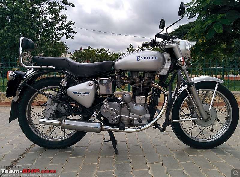
I own a royal enfield 2002 model which has a cdi ignition.i am planning to perform some mods in order to facilitate the cold start.
it has an exitor coil which charges the capacitor in side cdi unit,also there is a pulser coil which precisely gives the timing pulse according to the piston position .

Now in due course of time as the exitor coil( produces around 100-150v @ 3000rpm) winding becomes weak there fore is unable to produce enough voltage to charge the capacitor as a result lots of kicking is needed to start the bike..
To get rid of this issue i have decided to put a module which simply replaces the exitor coil.The module converts 12v dc(from battery) to 90v square wave ac @ 30khz frequency,this ac output is feeded to cdi unit,what i guess is that this mod would fully charge capacitor of cdi instantly & when kick is applied the timing pulse(from the pulsar coil) would triger the discharge the capacitor through scr tothe primary winding of ignition coil & would produce better sparks & hence better ignition.

i would like to seek advice from the learned members of the group on the feasibility on this prospective mod.
 
Hy SANDEEP,

Sounds like an OK idea. You would probably need to put a rectifier diode between the external pulse generator and the CD capacitor. If the output of the pulse generator is isolated you could use a bridge rectifier which would give full wave rectification and twice the capacitor charging speed. A low frequency rectifier would not be suitable. You would need a high speed diode.

You may also need to put a resistor between the pulse generator output and the CD capacitor so as not to upset the pulse generator when the CD ignition fires.

One thing you can check is the CD capacitor; these have a hard life and are prone to degrade. Changing the capacitor to a high voltage, high current polycarbonate type could solve your starting problems.

The other capacitor that can degrade is the capacitor across the ignition coil primary. If this fails open circuit the spark duration, and thus energy, will be reduced radically.

spec
 
Last edited:
Hello Spec,
Thanks for your suggestion,
the cdi unit i am using here is the stock one which was fitted in bike..it is an ac cdi unit...therefore what i think it already has an in built rectifier may be a low frequency one or it may contain a non polarized ac capacitor...(this is my guess work, as the cdi unit is a sealed one cant disassemble it.)
Yes i agree on degradation of cap;i wanted to ask about the value of resistance that can be attached between capacitor & pulse source.

Thanks
 
Last edited:
Hi, SANDEEP,

I would think that 22 Ohms 5W wirewound would do the job. Wirewound is good because it has some inductance.

spec
 
Last edited:
Hi Spec.
What can be done if the ac cdi already includes a low frequency rectifier...should i attach an additional hi frequency rectifier externally..if yes what would be specs of diode to be used.

Thanks
 
Hi Spec.
What can be done if the ac cdi already includes a low frequency rectifier...should i attach an additional hi frequency rectifier externally..if yes what would be specs of diode to be used.

Thanks

Hi SANDEEP,

Good point: a 2 Amp minimum, 600V minimum rectifier would be a good choice. The voltage rating is on the high side to be safe.

Put a 300V, minimum, 220nF, approximately, polycarbonate capacitor after the high speed rectifier and before the wire wound resistor.

Many rectifier diodes would be suitable, for example:
(1) 1N5190: https://www.digitroncorp.com/Documents/Datasheets/1N5186-1N5190.aspx?ext=.pdf
(2) STTHSL06RL: https://www.st.com/content/ccc/reso...df/jcr:content/translations/en.CD00002719.pdf

spec
 
Last edited:
spec,
do i need to enhance or boost timing signal from pulsar coil?
Afraid I do not know without a schematic of the pulsar circuit, but I think it is unlikely.

One question: did the bike start OK at one time?

spec
 
That sounds like a weak mixture rather than electronics.

Is the choke working OK?
Is the carb set up correctly, especially float level?
Have you got the correct plug gaps?
Are the HT leads OK.
Are all the leads etc perfectly clean?
Have you changed the plugs recently
What is the battery voltage when the engine is not running?

spec
 
Last edited:
yes sir, all of them are perfect in condition..on visual inspection i found the spark to be weaker...i even planned to rewind the exitor coil..in order to get better voltage hence better sparks...but dont know why the inductance of newly wound coil came out to be 0.5H instead of 1.3H which i expected even after more no of turns of magnet wire..(i used 38awg).
now the last resort is this 12v to 190v ac converter(**broken link removed**
Be careful not to put too higher voltage into the CD unit

spec
 
i would measure the voltage made in exitor coil while bike engine is at 1500-2000rpm (probably 90-120v ac;low frequency) & limit the output 30khz squarewave ac to corresponding voltage..

My aim is to start the bike in a kick or 2..

i hope 120v in would give a better spark even when the bike is running at 60km/hr..

any piece of advice spec?
 
yes..it is 2002 model royal enfield electra cdi...i have installed a heavier crank for better thump n feel..

Like this:

1259176d1404830577t-royal-enfield-electra-1-10-000-kms-completed-img_20140706_160049r.jpg
 
And is this the charging coil which you have rewound:

$_12.JPG
 
i would measure the voltage made in exitor coil while bike engine is at 1500-2000rpm (probably 90-120v ac;low frequency) & limit the output 30khz squarewave ac to corresponding voltage..

My aim is to start the bike in a kick or 2..

i hope 120v in would give a better spark even when the bike is running at 60km/hr..

any piece of advice spec?

The symptoms you describe are baffling. I can't understand the low inductance reading with more turns. Presumably there is a core in the coil. Is the core cracked or not clamped together well ?

substituting another 120V power supply sounds like a good move.

spec
 
Last edited:
Status
Not open for further replies.

Latest threads

New Articles From Microcontroller Tips

Back
Top