electrookie
New Member
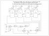
Hi all. I am using a CD4528 Dual Monostable Multivibrator and when it is first powered on, it starts the 1st clock. I want to get it to start up and NOT start the clock. It is being used as a 2 stage timer (4 stages shown in schem.) where the 1st timer must end (go low) before the 2nd timer starts. The attached schematic shows 2 4528's in use for 4 stage cascade timers.
2 problems exist. As stated above, at power on, both (all 4 actually) outputs are high and not necessarily for the designed time frame. I can open pins 3 & 13 and the outputs stay low at power up, but then the cascade will not start when triggered. So, I did this, then after power was on, I tied pins 3 & 13 to +V and the cascade starts when triggered. So what I need to do is replicate this sequence, bring pins 3 & 13 to +V after the rest of the circuit is powered up. So some kind of simple delay "should" work, but I can't seem to get it, with various ideas and designs I have tried so far.... HELP...
Now the 2nd issue is this: when the 4528's are built into the rest of the shown circuit, all the timers should NOT all start at the same time. They are supposed to cascade and NOT be re-startable till all timers are done. I'm getting confused trying to chase around the 1's & 0's to figure out why this is. Am I missing something here??? This circuit was originally shown in a Popular Electronics Mag. circa. 1995-1996. It look's like it should do as shown, but I have built it 3 times and know I have it wired properly, getting the same result every time. So I either built it wrong 3 times, or there is something else not properly shown in the design.
As always, I am not committed to the CD4528, I will use 2 555's (a 556) if it works. I just found this circuit and thought it was very cool and doable. Any other suggestions would be appreciated.
And I know that PIC's are the way to go for most of what I want to do, but I do not know PIC's (YET), and I want to get this all working now, not after I learn PIC's. So for now, NO PIC's Please..
Thanks guys....