Electro Tech is an online community (with over 170,000 members) who enjoy talking about and building electronic circuits, projects and gadgets. To participate you need to register. Registration is free. Click here to register now.
Welcome to our site! Electro Tech is an online community (with over 170,000 members) who enjoy talking about and building electronic circuits, projects and gadgets. To participate you need to register. Registration is free. Click here to register now.
Hi can someone help me on building a simple up down counter.. I am using cd4510 so is it requred to use cd4511 as the decoder to 7 segment and is it possible to use ldr as my input instead of switch?if i use hcf4510 does it work well with 74ls47?
there was a simple reason why there shouldn't be mixed threshold levels in the digital signal path . . . some of whitch may have been
driving power hungry logic from weak power cmos output just fails (threshold-level independent) coz F̅·dt=d(m̅·v̅) , A=U·dq=F·dr·dq=E=P·dt=m·c² from where P=f·A=f·q·U=f·F·dr e.g. the more power is required to 1) complete work "A" faster , 2) to complete more work "A" in given time "t"=N·dt=1/"f" , 3) to transfer more charge - "q" (electrons) , 4) change current "I"·dt="q" at greater slope (if ← dt is fixed then the greater the q the greater the I) , 5) change voltage "U" at greater slope , 6) move anything around "F·dr" faster as F̅·dt=d(m̅·v̅) -- the grater the "F" the greater the speed "v" or it's mass "m" or then move anything around "F·dr" further as -- the grater the distance "r" the more power it takes to transfer it there ...
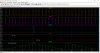
has Vdd 5V specified at it's datasheet -- simple test is to see if ones output can drive anothers output R2R not getting extremely hot by that in longer run ???
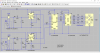
This one is the simplest I can get from google images..
It was for 3 digit but you just need to make 1/3 of the schematics. Hi/Low pulses enter the clock input would make it count.
This site uses cookies to help personalise content, tailor your experience and to keep you logged in if you register.
By continuing to use this site, you are consenting to our use of cookies.