Continue to Site

Welcome to our site!

Electro Tech is an online community (with over 170,000 members) who enjoy talking about and building electronic circuits, projects and gadgets. To participate you need to register. Registration is free. Click here to register now.

  • Welcome to our site! Electro Tech is an online community (with over 170,000 members) who enjoy talking about and building electronic circuits, projects and gadgets. To participate you need to register. Registration is free. Click here to register now.

CD4017 help.

Status
Not open for further replies.

axro

New Member
I'm looking at the datasheet for the CD 4017. I'm having some problems understanding some of these numbers.:

4017-jpg.31609


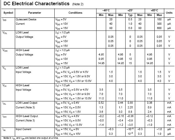
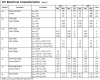
Why is the high level output current negative numbers. Isn't the High Level ouput current the current that each "port" puts out when it becomes active?
 

Attachments

  • 4017.jpg
    4017.jpg
    64 KB · Views: 7,855
I realise that. But wouldn't Output High be sourcing? Why would sourcing be negative.

The manufacturers use the convention that POSITIVE current flows INTO a pin, and NEGATIVE current flows OUT of a pin. If you see the -, that should automatically make you think "current from the pin to an external load"
 
I'm just looking at the datasheet. But i suppose LED's for right now.

The high-state output current of such CMOS devices is pretty whimpy; not enough to drive LEDs directly. Use a hex inverting buffer (4049) between the 4017 output pin and the LED. Wire the the anode of the LED to Vdd, and put a current limiting resistor between the LED's cathode to the output of the buffer
 
How are you supposed to know when a manufacter is using - flows from the pin or + flows from the pin?
 
How are you supposed to know when a manufacter is using - flows from the pin or + flows from the pin?

Read the data sheet and it is defined that way. It goes all the way back to DTL/TTL logic which was good at sinking current, and crummy at sourcing it, so I guess the convention attaches more importance (positive) to sinking...
 
Read the data sheet and it is defined that way. It goes all the way back to DTL/TTL logic which was good at sinking current, and crummy at sourcing it, so I guess the convention attaches more importance (positive) to sinking...

The 4017 is CMOS though isn't it?

So Is High output Sinking or Sourcing in conventional terms? Say I I connect the Anode(Positive) end of an LED to an output and th cathode to ground. Would it light on High output or Low?
 
The 4017 is CMOS though isn't it?

So Is High output Sinking or Sourcing in conventional terms? Say I I connect the Anode(Positive) end of an LED to an output and th cathode to ground. Would it light on High output or Low?
Whether it's CMOS or not does not affect the direction or polarity of current at a terminal. A high output is source and a low output is sink.

The LED would light when the output is high. Obviously when the output is low the anode and cathode are at the same potential and no current flows.

The normal convention for all terminals, independent of whether the terminal is an input or output, is that an input current is + and output current is -. Thus you don't have to determine whether a terminal is an input or output to know which way the current flows for a particular polarity. For example an output sinking current or an input drawing current both have a + polarity.
 
Last edited:
The high-state output current of such CMOS devices is pretty whimpy; not enough to drive LEDs directly. Use a hex inverting buffer (4049) between the 4017 output pin and the LED. Wire the the anode of the LED to Vdd, and put a current limiting resistor between the LED's cathode to the output of the buffer
Texas Instruments show the output current of most of their ordinary Cmos parts at three supply voltages and at any load down to a dead short.

The CD4017 has a typical output current of 17mA or a minimum of 8mA into a 3.5V white or blue LED when its supply is 10V and no current-limiting resistor is needed.
Its typical output current into a 2V red LED is 19mA but then the output transistor dissipates 152mW which is too high so a current-limiting resistor is needed when the supply is 10V.

Where are you getting those numbers? If Vdd is 10V it says the typical High current is 900uA.
 
Where are you getting those numbers? If Vdd is 10V it says the typical High current is 900uA.
Look at the datasheet of the CD4017B from Texas Instruments.
Maybe you are looking at an old CD4017A datasheet.

With a 10V supply and a 0.5V output voltage loss then the typical output high current is 2.6mA at 25 degrees C.
Then look at the graph. With a 10V supply the typical output high current into a short to ground is 19mA. Into a 3.5V white or blue LED is 17mA.

The output current of most CD4xxx ordinary Cmos logic ICs are the same.

Here is the typical output high current graph from the datasheet:
 

Attachments

  • CD4017 output current.PNG
    CD4017 output current.PNG
    28.2 KB · Views: 630
The typical current limiting is shown on the graph.
There is another graph showing the minimum current limiting.
They do not say what is the max current limiting but I think it is not much more than the typical.
 
Look at the datasheet of the CD4017B from Texas Instruments.
Maybe you are looking at an old CD4017A datasheet.

With a 10V supply and a 0.5V output voltage loss then the typical output high current is 2.6mA at 25 degrees C.
Then look at the graph. With a 10V supply the typical output high current into a short to ground is 19mA. Into a 3.5V white or blue LED is 17mA.

The output current of most CD4xxx ordinary Cmos logic ICs are the same.

Here is the typical output high current graph from the datasheet:

This is probably really a dumb question. But you said into 3.5V LED it would be 17mA. Did you get that number because of the voltage drop of the LED? Making 6.5Volts?

Also just for the sake of learning. If I were to take a 150ohm resistor and connect it from one of the pins to ground would I fry the chip then? If chip output is 10v then it would have to source close to 70mA. So would the chip overheat or would it just only put out it's max current of 20mA or w/e it is.
 
Last edited:
The typical output current of a CD4xxxB into a 3.5V LED when its output is high and the supply is 10V is 17mA as shown on the graph.

Into a 150 ohm resistor the typical current is about 18mA with 2.7V across the resistor.
 

Attachments

  • CD4017 driving an LED.PNG
    CD4017 driving an LED.PNG
    28.3 KB · Views: 524
Last edited:
Why is there a 2.7v voltage drop across the resistor? I wasn't aware the resistors had a voltage drop at all?

You didn't really answer my question about the resistor.

Even if there is a 2.7volt voltage drop. The current should be I=7.3/150= 48.7mA. So is the chip going to try to source that much and overheat, or is it just going to source 18mA that is it's max?
 
Hello Axro,
Look at the graph I posted of the typical output current from a CD4xxx.
Its max current (into a dead short) is 19mA when its temperature is 25 degrees C and its supply is 10V.
The graph shows the voltage dropped across the output transistor in the chip with load currents. With a 150 ohm load then the voltage dropped across the output transistor is 7.3V then the voltage across the 150 ohm resistor is the remainder which is 2.7V. Ohm's Law calculates the current to be 18mA, not 48.7mA and not 66.7mA.
 
Status
Not open for further replies.

Latest threads

New Articles From Microcontroller Tips

Back
Top