Hi guys.
I didn't know where else to turn!
I have tried the BMW forums with no success but now it's time to ask the experts.
My daughter has a BMW X3 which she has spend every penny of her saving on only to discover now it's getting darker at night that the rear lights are only partially working and lowland behold... The seller can't be contacted!
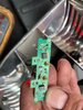
I have managed to strip the sealed units of the rear lights down to find that some if the leds on the board are not working (both rear lights have the same issue)
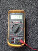
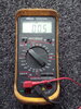
We are getting power to the two first led's on the side, then it runs to the next three which don't work. When I cross the two legs of the next led the final two work so I'm assuming that one of the led's have blown.
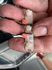
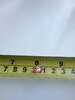
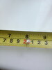
I have removed the led I suspect has blown but no way of identifying it and don't understand the formulas on how to work out what we need.
I have taken a few pictures and am really hoping that someone may be able to help is out as to replace the rear lights on this car would be nearly £300 which she can't afford.
I would appreciate any help on this, I am confident with soldering etc but I am purely a remove on and replace with another kinda guy
I would also like to thank in advance any help any person may be able to give.
Thanks again.
I didn't know where else to turn!
I have tried the BMW forums with no success but now it's time to ask the experts.
My daughter has a BMW X3 which she has spend every penny of her saving on only to discover now it's getting darker at night that the rear lights are only partially working and lowland behold... The seller can't be contacted!
I have managed to strip the sealed units of the rear lights down to find that some if the leds on the board are not working (both rear lights have the same issue)
We are getting power to the two first led's on the side, then it runs to the next three which don't work. When I cross the two legs of the next led the final two work so I'm assuming that one of the led's have blown.
I have removed the led I suspect has blown but no way of identifying it and don't understand the formulas on how to work out what we need.
I have taken a few pictures and am really hoping that someone may be able to help is out as to replace the rear lights on this car would be nearly £300 which she can't afford.
I would appreciate any help on this, I am confident with soldering etc but I am purely a remove on and replace with another kinda guy
I would also like to thank in advance any help any person may be able to give.
Thanks again.